Ringforcement
The “ringforcement” related webpages had detailed multiple applications, testing, concepts and modeling. The current page was the most generalized description, edited for 2026. Original links and related pages are currently omitted.
Ringforcement is a freely adjustable, ringed reinforcement for building structure, and has been prototyped and tested at a very small scale. The purpose was to serve efficiency along with flowing curvature, using common, readily available materials. Primarily single handed efforts were used over the years by myself. The findings are that distribution of strength is simplified and building costs are potentially lowered, because efficiency is increased. Examples of ferrocement are described here, beginning with illustrations. This simple model is drawn first:

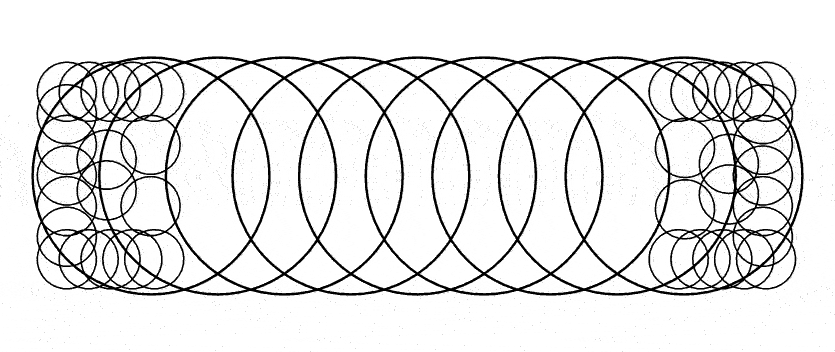
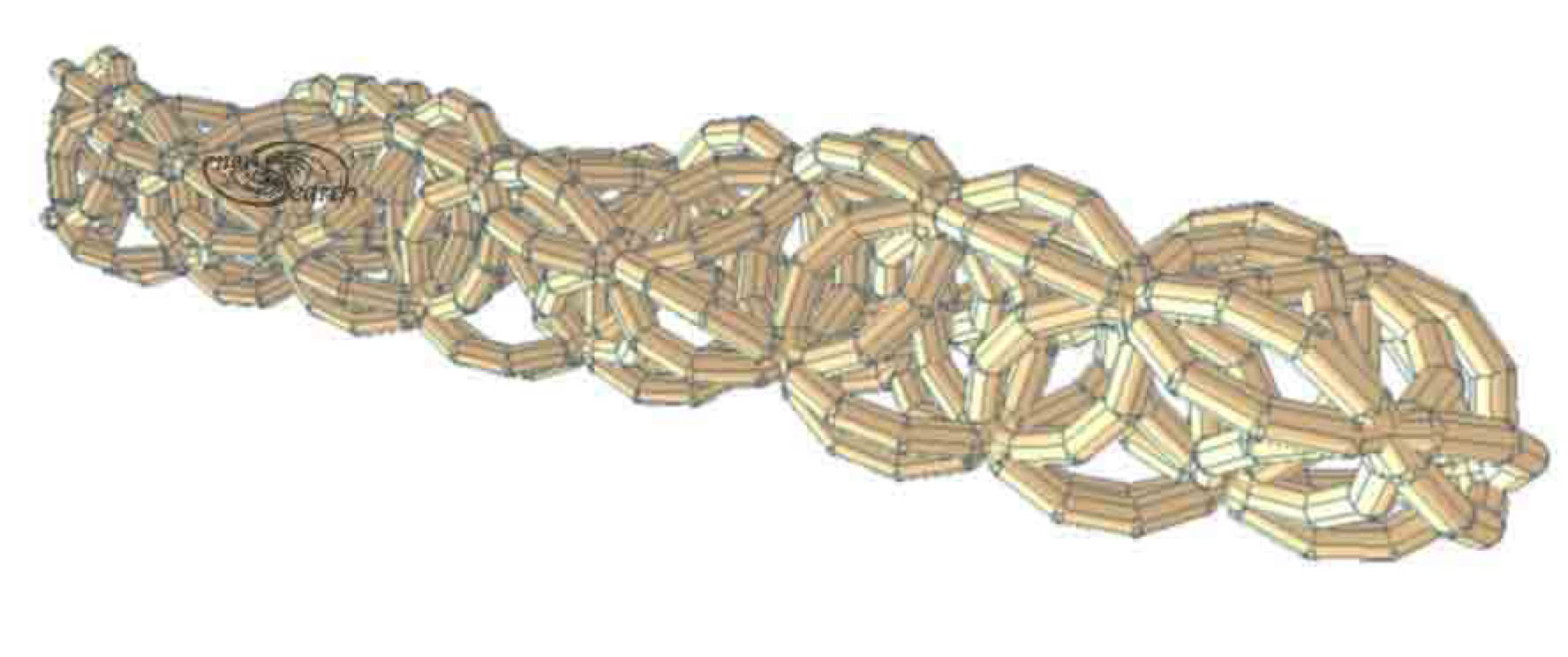
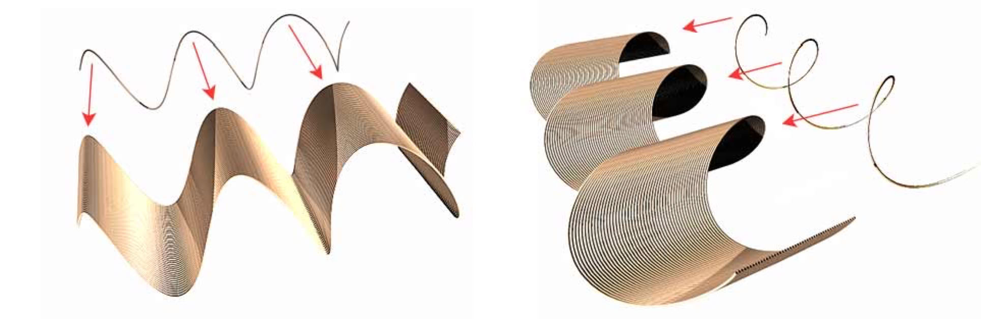
The first model represents 9 overlapping rings which form a chain like reinforcement, made from loose rings bonded by adjacent bulk material, instead of chain linking, for simplification producing composite structures. The infill serves as intermediate knobs between overlapping rings, thus joining surfaces as needed by design, across flats, curves, angles, corners or extensions, and all by means of less laborious extrusions rather than by measuring, cutting and fitting more slowly. Loose rings are not currently available as a cheap reinforcement, and so this writing has presented ideas and prototyping models, to investigate and possibly encourage ring production, as a profitable possibility, and has here been termed ringforcement since 1998.
Economical filler material, (like aggregates in concrete) is bound within each internal ring space, and overlapping rings share the bound up filler material The same bulk material binds multiple overlapping rings together due to close proximity. Closely embedded reinforcement rings of high tensile strength resist outward bulging force. The red arrows indicate the inward direction of binding. Next a side view emphasizes that these rings overlap but do not loop through one another. The angle and separation has been exaggerated. A solid red coloring indicates ring integrity, geometrically speaking, just to make the separation clear.

Stronger rings bind cheaper internal bulk, making a stronger product over all. Any shape or form can be economically reinforced with additional benefits*. Suppose the same 9 rings were used to reinforce a close fitting, rectangular, composite slab. The corners are not reinforced by the larger rings. The ends lack equal reinforcement density. In this case, smaller rings could provide ample reinforcement coverage as in the third model below.
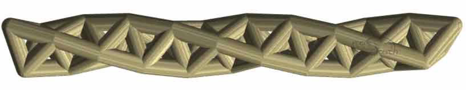
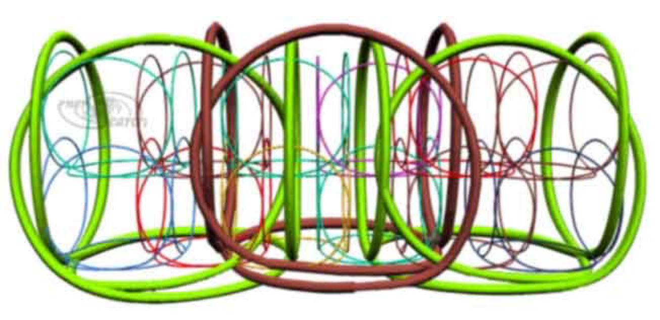
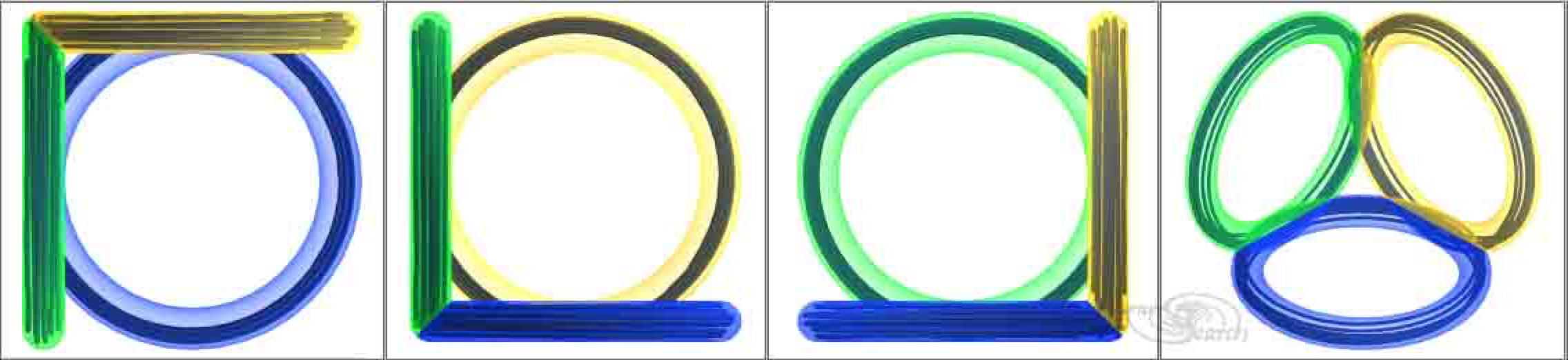
The next model below introduces more modes of reinforcement. It visualizes composite ring framing in schematic colors. Tailored ratios of bulk material and reinforcement material can be engineered or variably stylized. Two styles of flat-helical truss work are modeled together. The somewhat, triangulated truss pattern is applicable for bridging or spanning functions. The key elements are reinforcement loops (or "rings") in dark colors which reinforce the bulk composite zones. The bulk thoroughly encases the reinforcement but considerable weight savings are achieved by minimizing bulk zones to volumes which are near to the reinforcement, (blue zones). Instead of straight struts, reinforcement rings encircle outer perimeters of cheaper composite rings, (where reinforcement most benefits the composite ring). Also see more detail under space frames.) Large open spaces between rings theoretically emulate characteristic truss hollows. The flat, helical reinforcement coils are completely encased (green zone), to provide a suspension cable effect. Flat coils are also encased in the orange zone which comprises the main "backbone". Contiguous bulk material alone "welds" together effective- chains of reinforcement. Without bulk material, flat coils are freely movable as loose wires. The larger individualized style, (blue) or the fine-diffuse style, (orange-green) can be used separately or combined.

Ringforcement is somewhat modeled upon theories of physics, like atomic ring bonds. Ring overlaps compare to electronic bonds. or shared electron shells. Three space frame rings are next illustrated to show that composite rings can bond together and that composite ring structures can partly share volumes. The black coils represent reinforcement rings and the colorful bulk rings represent compressive material or concrete.

The illustration above portrays that the reinforcement material (coil) performs more valuable work when in "wraps" the bulk material within it's bounds. Reinforcement rings achieve more by encircling and therefore binding the bulk material (like concrete or other composite materials). Two relatively low cost composite materials can achieve more functional strength, due to this strategic arrangement of both materials.
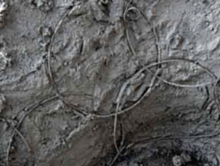
Thicker coiled wire for reinforcement and singular rings were embedded in a wall.

Welding, weaving, tying , clipping, clamping and adhering methods have been explored for research. However the simplest methods were of particular interest: A suitable bond for primary reinforcement members can be achieved solely by embedding strongly tensile ring shaped configurations into lesser materials, which paste, compress or cement the bulk together. Ferrocement and steel reinforced concrete are composite structure types that are much stronger than the bulk material alone and vastly more economical than the stronger material alone. Precise specifications can vary widely to meet particular composite criteria. The following benefits are postulated for ringforcement in concrete and other composites generally. This list can apply to many kinds of products and processes.
1) Normal, bulk, concrete shrinkage and general stress can be fractionate, to distribute stress.
2) Linear tension likewise tends to bind all sections.
4) Additive building with tensional and compressive components in-situ reduces costs, (given efficient supply ).
5) Labor cost savings by simplified tooling, and supplies.
6) Less processed sourcing reduces environmental impact.
7) Ring meshes readily fit more customizing and budgets.
The primary anticipated caveat is that meaningful testing is expensive. Some innovative technologies can be stalled or forgotten. However small examples are notable in low cost structures. Ringforcement enables new and old methods.


Page undergoes formatting while the editor occasionally prioritizes other work.
Ringforcement can be configured in flat, thin-shell structure like ferrocement or in concrete slabs. Any resin system, lay-up application, lamination process, or any other application may benefit as well. Rings can be continuously inserted within live extrusions. Ring emplacements during live extrusions of composite bulk is applicable both to hand labor as well as in automated systems. Rings can be directly placed in overlapping patterns, as the fill material is applied. Current material availability favors use of continuous wires, filaments or else long bars. Roving filaments (like glass or many carbon derived filaments) can be simply spooled into desired patterns as their flexibility may allow simpler handling. Stiffened wires, bars or coils may require customized tooling design. Stiffer materials often imply greater strength and reduced elongation properties, (which are highly desirable generally). Nevertheless, simplistic, hand lay-up can be readily mastered. Easy hand work translates into easy robotic development as well. Ringforcement potentials are further expanded in 3D space frame composites, as follows. The simplest 3D truss chains are triangular. Below is an example which may be additively built with bulk ring modules (which encase reinforcement rings inside the bulk rings). Isotropic triangulation at each segment stabilizes the space frame. Many truss chains can be lapped together, built individually in steps or fused together as one whole.
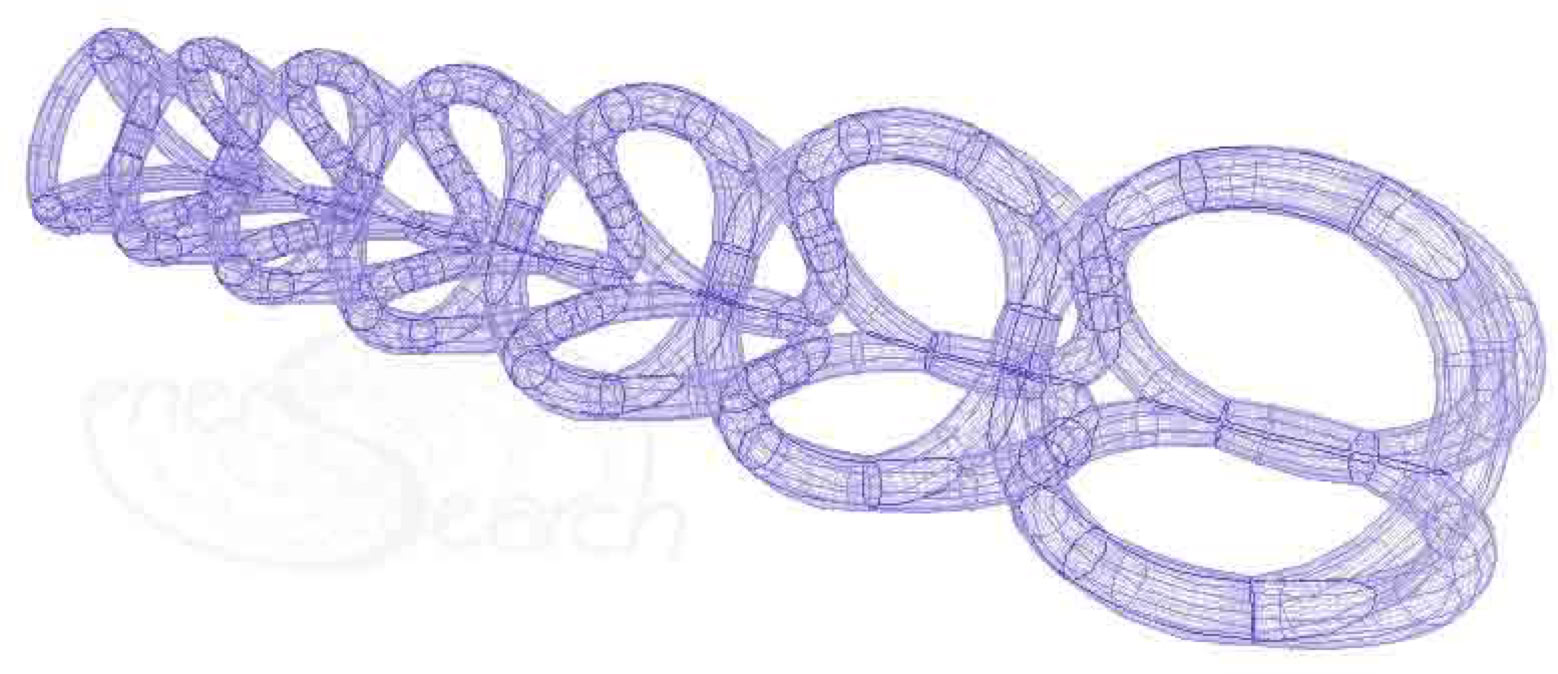
Above is a CAD example visualized through ACIS geometry. Adjoining rings share volumes. Otherwise ringed trusses can be nested together with a draft angle to permit later assembly. A variety of reinforcement patterns can be "bonded" inside the bulk ring or shell. A better bond may be found than welding, tying, clipping or bolting. More easily, bonds can be achieved solely by embedding stronger ring-shaped configurations into cheaper materials, like concrete, which largely comprise the bulk. The key is that rings are strategically overlapped close enough to "share shells".
Skip past RP notes to cube ring reinforcement.
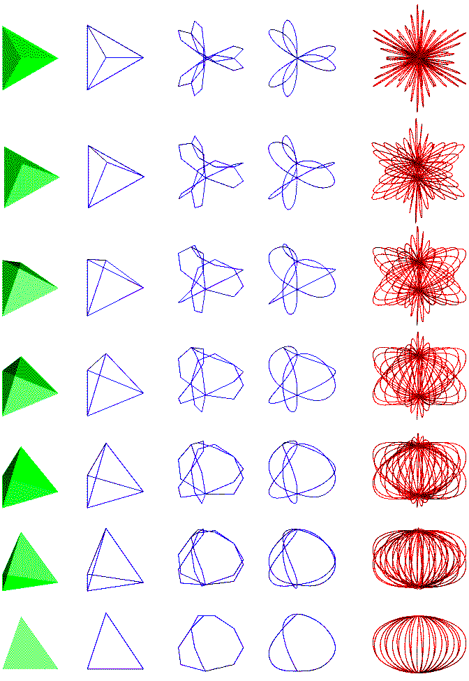
Additive molding processes like Rapid Prototyping (RP) can produce shared-shell trusses. Next below are modeled similar rings but mapped onto a tetra helix formation of tetrahedrons. The tendency for intersection interferences most easily adapts to additive-building processes as found in RP. Yet for electronic polarization purposes, tetrahelix mapping possesses promising qualities. (It is a matter of finding the right ring relationship or the code, as it were). Ringed resonators may serendipitously transform forces in new ways.
Next a tetra helix ringed arrangement having thicker rings, (but still with low resolution display). The rings here share more volume than the intersections alone.

By contrast, the original tetrahelix discovered by Bucky Fuller is completely formed by straight segments joined together as tetrahedrons. (See Below).
Cube rings are considered next. Three dimensional reinforcement "rings" may be bent and twisted in place or else be placed with precise intersections set in advance. The critical structural bond can be formed solely by well overlapped rings which are well embedded in a molded material. Modest, real life scale models have worked very well. A 3D modular structure is additively formed by overlapping 3 D reinforcement units.
Above is a versatile structural reinforcement array (to be embedded in a composite material), based on cubic modules. The simple cubical form is easily understood. Overlaps can be achieved by a draft angle which nests the cubical reinforcement units together. Unit cubes can overlap more densely than drawn to achieve very dense, well dispersed reinforcement, where applicable. A favorite, little known proof for well dispersed reinforcement can be deduced, click here. (It is expected the ferrocement movement may have more conclusive engineering proofs as well, not readily available at this writing).
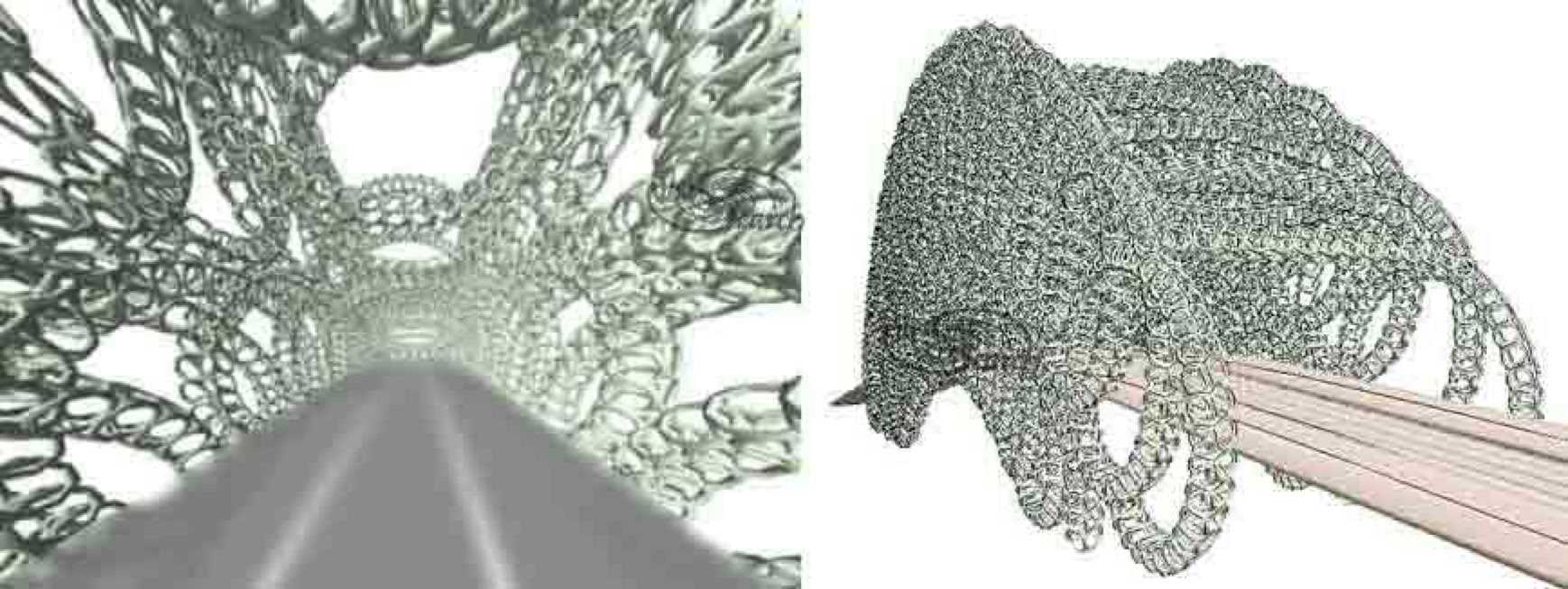
While cubes naturally have six faces, overlapping cubes will form with as few as four ringed-faces. Unitary manufactured reinforcements could look like picture on left above. A lightweight fiberglass space frame, made with composites or plastic, could nest together for reinforcing lesser composites, (and for shipping). The ring faces comprising one reinforcement module (or cube) can be made from a continuous bar, wire or filament, (as in the above model to right). Consecutive flat loops are twisted at junctures, orthogonal to correctly position adjoining loops. Loop intersections can vary for different applications. The ends of the reinforcement member may simply extend their looping, like key rings do, or they may have hooks like concrete bars have. For economic advantage, the lesser material can be used for terminal anchoring, within each reinforcement unit, as if extending older concrete practices. Computer controlled bending and twisting would allow on site, precise cubic scaling. The model below demonstrates a conceivable application for scaled ring reinforcement cages (embedded in concrete). Rings have been carefully scaled, overlapping row upon row, to form a smooth outline of many modular ring cages. It might allow highway underpasses to more efficiently weave through interfering support structures, in congested traffic areas. Where traffic control becomes critical, smooth highway paths relieve and improve traffic flow. Interfering highway routes might conceivably be addressed in this manner.

Such a model as the above support structure will require stronger reinforcement at mid height where the cross section narrows, (and perhaps higher specification concrete as well). Note the natural state of diminished ring density along the structure edges. Compensation can be made to increase edge reinforcements and near surface strengths. A close-up detail pictured next, shows how naturally diminished ring density may be supplemented with smaller rings added near all surfaces. The schematic colors are for individual cube- ring distinction only. Multiple colors assist the eye to see how 3D meshes can be "woven", simply by overlapping individual cube rings.
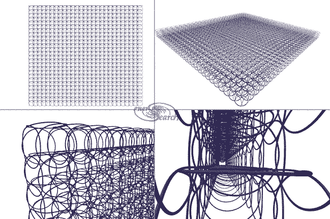
The 3D chain bridge model (next below) will further demonstrate annular applications in space frames. The perspective visualization below, has 2792 solid, cubic ring structures joined in tandem sets. Space frame cube rings form long, self intersecting chains. A bridge structure of this type could conceivably be made with extremely durable and high strength composites.
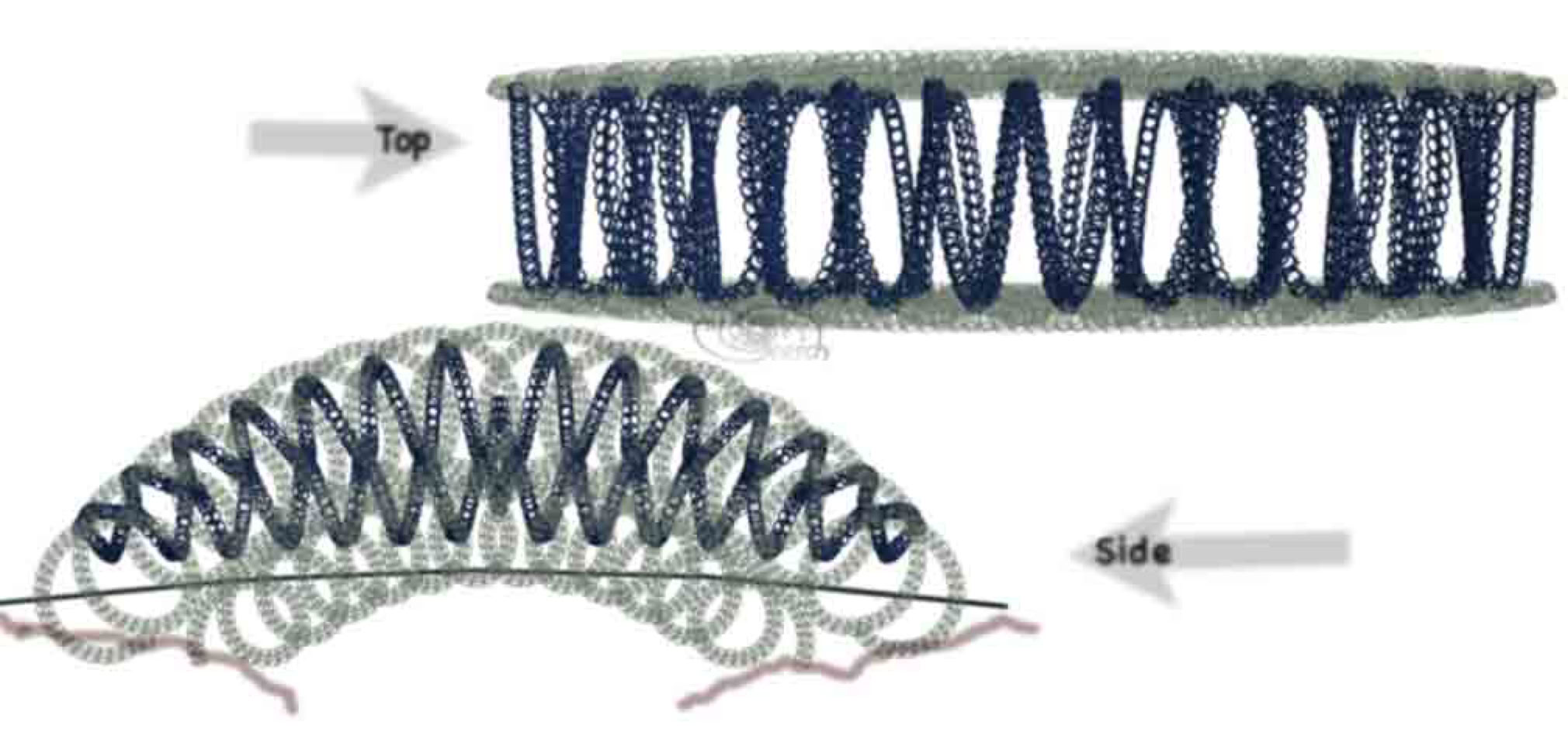
Next below are the side and top views of the bridge which reveal a dual helical cross tie concept. The helical tie paths are tapered to accommodate the bridge arching. The bridge sides are made partially transparent to better reveal the spiraling tie. (The spiral tie is shaded darker for distinction). The cube ring chain truss can accommodate practically any desired shaping. A precise and cost effective software, formZ made possible the conception and generation of this 266MB model within several days on an "old" 2003 computer, (over 3 years old when modeled).
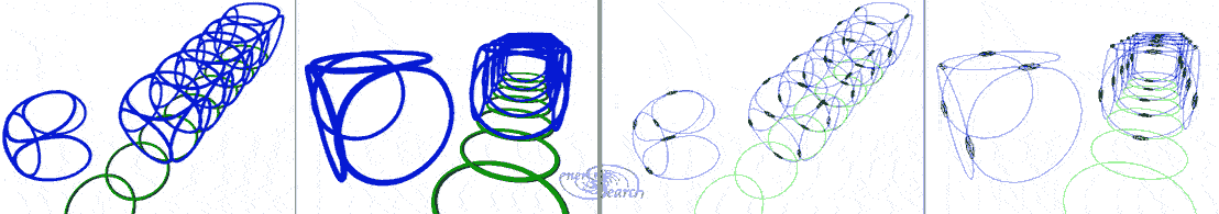
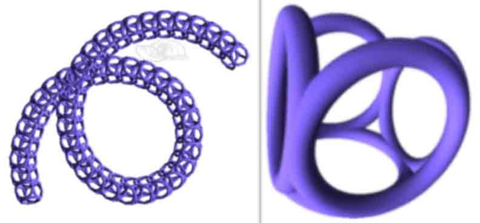
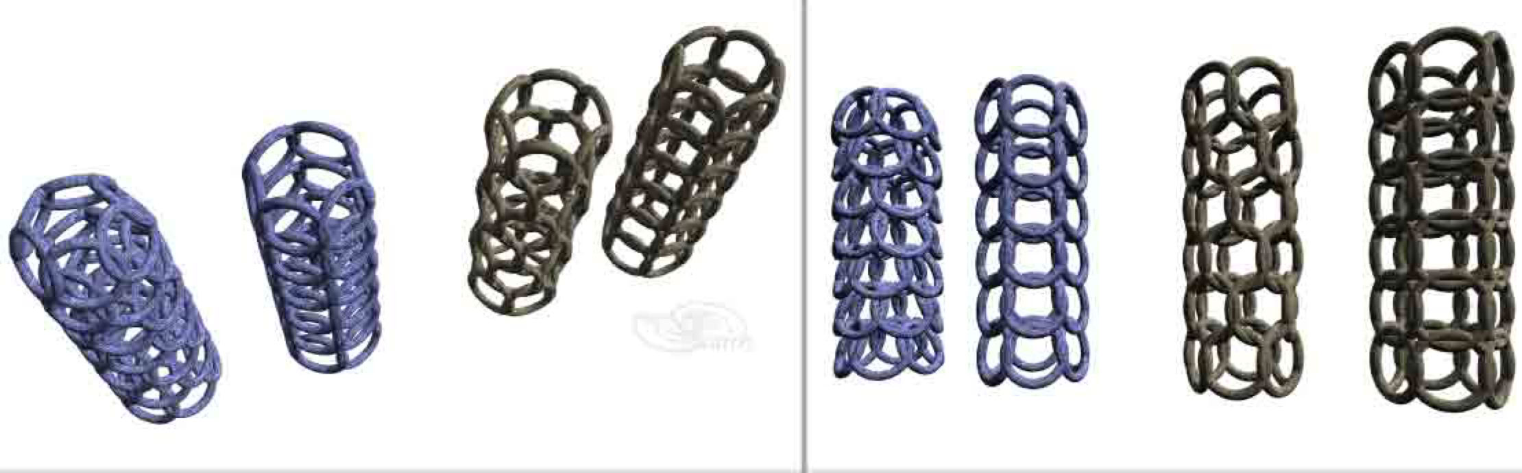
Next below is a subdivision model (in blue color), to better show cubic ring elements. Five solid rings, to be molded from engineered composite materials, are fused together. (See model on right, below). Such fusion would approximate geometric booleans, implying that the rings will partly share volumes. Five ringed units can overlap in tandem and together form customized, long 3D chains or chain trusses. This could conceivably be achieved by use of carbon filaments and the most resilient kinds of concrete. (Ductal® and other competitive products may be strong enough for this purpose.) Mix designs could vary with strong- light weight composites on top and denser composites towards the bottom. To the left, below, 45 X 5 rings form a single turn of the helical- lattice- framework. Forty eight single-turn helical lattices make up the bridge sides This involves many shared ring volumes which could in fact be molded with cementitious methods and computer aided construction. Engineering geometry would be derived from 3D boolean unions. High precision ACIS was used in modeling these displayed images.
Yet a further model subdivision sheds light upon possible ring fusion, (pictured below). Three rings are pictured in three colors for distinction. The rings are semi transparent to show multiple reinforcement rings in black, circling the outer portion of concrete rings. The inner-circumference of each ring require less reinforcement due to the compressive function of this inner zone. Therefore reinforcement is kept to the outside where it does excellent work. Reinforcement rings can weave orthogonal to encircling all bulk rings. An advantage of reinforced 3D cube rings is in effect, to leverage the tensile strength assets upon a compressive space frame of concrete. Yet the inner ring volume of concrete alone, without central bulk, (without a filled "donut hole"), fulfills the significant structural framing. The "large donut holes" are weight savings and significant cost savings.
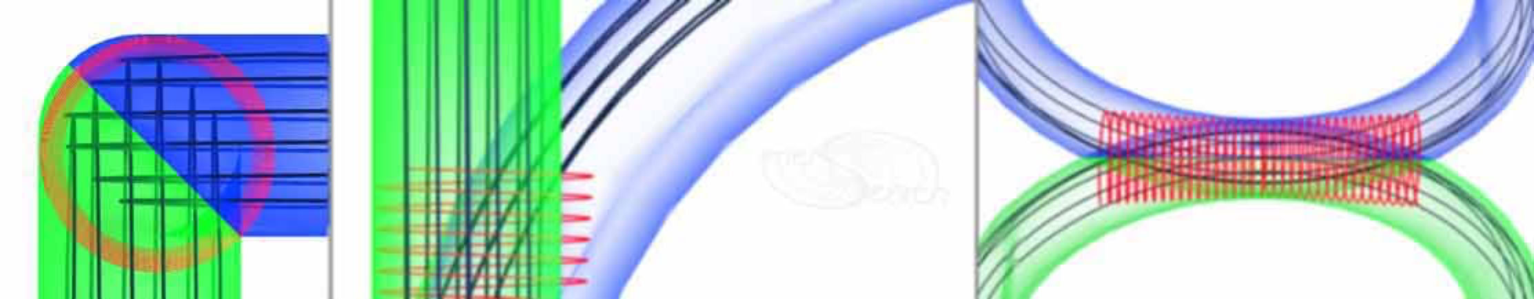
Finally, a series of close up ring junction details may be considered. A key feature of space frame-ringforcement is the shared shell volumes, (volumes of the bulk ring material or in this example engineered composites). The (black) reinforcement rings penetrate orthogonal through adjoining reinforcement rings. Ring segments are able to do this, in contrast to solid meshes which cannot inter penetrate intact. Ringed"meshes" easily interpenetrate, both by hand labor and also easily adapt to robotics or rapid prototyping. Thus some additional "effective rings" result within the overlap zone. Additional orthogonal positioned, smaller reinforcement rings, (red in pictures below), can be placed to reinforce the shared shell zones. These smaller (red) reinforcement rings must pervade the zone to help resist shearing forces. (Note that 4 red ring sets like the first image on this webpage, appear in the next picture below.) External tension stresses conducted along the main, large reinforcement rings present a delaminating potential which can be arrested by smaller (red) ring configurations.

Flat individual rings, flat coils or coils wound about the main reinforcement rings, may reinforce the large reinforcement junctions. Another very key feature of ringforcement generally is that by significantly overlapping reinforcement rings, the stresses at junctions are distributed along the said rings. Instead of localizing ring junctions to a single point of intersection, the junctions are diffused broadly. The broad diffusion of stress will therefore not present compounded stresses at one single point along a reinforcement member. Any point of greater stress, within the composite can receive stronger composite ingredients. Other portions of the composite may be treated with cheaper composite ingredients.

The triangular-ring truss framing (presented earlier), could be compared with the cubic form , on a basis of equal total weights and bridge spans. Likewise other polygonal space frames deserve comparing also. Six sided or hexagonal forms of "hex ring" framing is modeled next. It would be interesting to compare competing geometries for the material consumption required for equal span performances.
By contrast, flat chains essentially lack cross sectional triangulation, (next model below). A stable 3D space frame stabilizes along three axes, at minimum.

There are additionally many, natural, polyhedral patterns upon which rings can be "mapped". Ringforcement thus can create "egg crate" surfaces or 3D woven effects. Traditional basket weavers are among the most prolific originators of many such patterns. Following is a 3D mesh frame work which is perhaps the easiest to produce. (The original page for this 3D mesh is linked here).

It is to be made from stiff wire which can easily store latent energy during the act of quick production. The most readily available wire was used. It is MIG welding wire. First the wire must be appropriately configured in a coil, somewhat like the coil pictured below. Next the coil is simply bent over a hard edge while being firmly held on both sides of the hard edge. Next the coil is released. The latent energy which was stored during bending, will distribute these bends such that a conical or dome like framework is instantly formed!! The aforesaid latent energy alone fulfills the intricate labor of mesh or dome formation. Therefore it is automation in itself. This framework can make up a reinforcement unit to be additively combined in a building process.
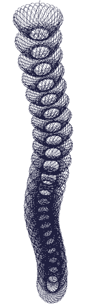
By Stacking coil- ringed coiled arrangements, columns can be formed. Flat coils and vertical coils both work.
Spinductor
"Next Inductor"
Concepts for Antennae
(Here is a link to electrical coil explorations, involving flat spiral coils of wire.)
To be added: The relationship of the helix to the tetrahedron using zero-radius paths for the helix formation.
Primal Tetrahelix Link
The earliest 3D cubic RIngforcement conceptualization work can be seen on this link. In addition other early visualization work on building blocks for walls, including a concentric 3D cube ring is to be found on this additional link. (It has also been included further below on this www-page.) T
Ringforcement benefits multiple scales of endeavor. An individual builder or entrepreneur is enabled to produce structure at relatively much lower cost, by use of embedded annular reinforcement. The very lowest equipment and material investments are required, regardless of which material types are chosen, to produce commensurate structures. The ultimate structural strength is postulated to essentially be equal for annular-embedded reinforcement, as it could be for welded, woven or tied reinforcement of the same configurations. Furthermore, it is postulated that comparing pound for pound, (or kilo for kilo), that annular or helical geometries of reinforcement will economically out perform purely linear shaped reinforcement. A large enterprise could potentially also benefit through labor reductions. Any scale of manufacturing could benefit through resultant efficiencies. Ringforcement is available for use by any entity without need for license or permission under the United States laws governing non profit corporations who freely and charitably serve the public good.
Ordinary, individual "O" shaped rings could also play an important reinforcement role.A manufactured product example which could become readily accepted and easily tested in the the concrete industry would be an "O" ring. The sizes of such rings could vary in a manner equivalent to sizing of concrete aggregates. One could add multiple sizes of rings to a concrete mix in order to improve it's strength characteristics. Such rings could be manufactured using strong plastics, glass filaments, or metals, like steel. The impetus for trying such products could come from the widely accepted concrete practice of adding fibers to concrete, grout and mortar. Various types of manufacture are possible. Already existing are suppliers making wire key rings. These could be readily purchased, mixed and poured into concrete test cylinders. Another approach experimented with was to convert a MIG welder into a continuous ring former which cuts the wire and terminates or welds it in one step. It was found that welder arcs can cut the wire while terminating the ends with swells. The swells alone may serve somewhat as anchors. Yet a preferred may utilize cutting combined with welding individual rings. This experiment is still in the debugging stage and lacking funding. A further concept may yet outperform these welding methods. "O" rings could otherwise be directly extruded through manufacture. Ordinary smoke rings are a practical example of how simplified extrusion processes could work, but utilizing the appropriate ingredients for manufacture. Direct extrusion of rings could save the step of wire manufacture. Ringed extruding could simply be a hollow extruded member shortened to provide consistent radii like donuts or tori.
This page still needs much updating. Eventually all ringforcement related links of this site will be listed, here are a few far reaching, "ring related links" .
Comments are invited. Constructive cooperation is offered.
In craft history, worldwide, some good examples of annular structure are noted in baskets, weaving, nets, twines, fabrics, chains and chain mail. Concrete was most noticeably introduced and understandably documented by the ancient Romans. Ringforcement recognizes a gravitational form of ring reinforcement clearly employed in a concrete structure named the Pantheon. Literature widely documents many aspects of the world famous building. The massive weight of the outer walls maintains a ring like structure which holds together and supports the massive, domed roof, still intact today.
Following are some earlier works published on the web concerning ringforcement.
Building Blocks
The "blocks" are formed in place by the suspended extruder, (slack wire robot). Here, each extrusion is referred to as a modular "block". Freshly extruded "blocks" can be placed to form course upon course, (similar to masonry construction). In masonry, solidified blocks permit immediate height gain. Fresh concrete needs support of some kind to gain wall height. Methods to substantially stiffen concrete are well known, (such as by use of much larger aggregates, use of fly ash and other additives like fibers. A yet further increase in stiffness may be obtained from fibers made into mini-rings which will reduce concrete slump still further). Fresh concrete of light enough weight could otherwise allow for this height gain, (without slumping). Concrete slump normally limits free standing formation due to slump caused by aggregate heaviness. Insulating aggregate (natural, manufactured or recycled) and various cement admixes may be designed to largely overcome slump and improve cement curing. A matrix of reinforcement rings partially acts as concrete forms, linking all parts of the fresh extrusion as one monolith.

Three directional linkage within each block and with adjoining blocks constitutes a highly distributed armature. Three directional linkage clearly outperforms one or two directional linkage. The inter block linkage provides considerable three-directional-stability in cured concrete. Combining tensile linkage, insulation and load bearing into one building block package greatly streamlines the automated process. A machine made to form one such block can conceivably be programmed to build thousands (assuming the attendant keeps up with supplies and command).


While four rings may be bent to form reinforcement for one single block as a building component, there are yet other ways to achieve the same reinforcement aims. Many blocks can be formed with long segments of flat spiral or flat helical coils of reinforcement material as pictured above. Only the ring reinforcement is shown, to transparently represent how each block could link together. Each face of a cubic "block" is provided a ring. Each ring is situated to link with rings of adjoining "blocks". However, where blocks are stacked together in a wall, each block could share and reduce the number of rings to advantage. All exposed faces of each block are provided rings. However connecting block faces can share a ring with neighboring blocks. For low rise structure, small gauge wires are assumed most appropriate for economy and adequate strength. Synthetic filaments are also worthy of study, in search of overall economy and durability. Placement of ring formations as drawn may be achieved with ring forming machinery. In absence of such machinery, hand made versions have already been built and studied internationally.
Large scale concrete structures will also likely benefit from this building technology. Many possibilities are conceivable, being most dependent on the scope of development. Dimensional analysis software would greatly help to determine optimum properties like material gauges, relative to types of concrete mixes to be used. 3D models (like those illustrated here), could quickly compare differing ring and admixture properties to identify the most worthy real world candidates. With this analysis software, design files specifying many alternatives can be readily compared.Next below, yet a further interesting ring configuration is shown. Three rings aligned with X,Y & Z axes respectively, are joined at six intersections. In practice the the rings could be placed directly in arrayed matrices and stabilized by the concrete alone. Or the rings could otherwise be joined by "hog rings" or the like, in triplet-XYZ form as shown, in advance of the concrete aggregation.


0ddress.gif
The First Ringforcement WWW-Page of the 1990's Follows
Research by Bo Atkinson
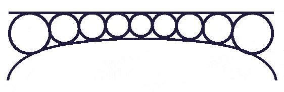
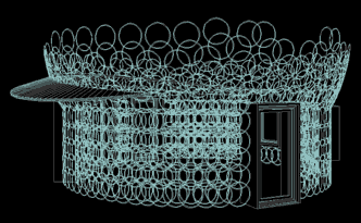
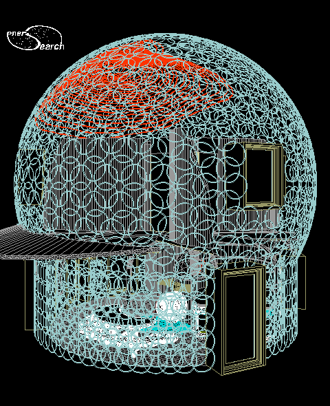
A postulated synergy of ferrocement, concrete, masonry and curved construction, a combined building method. The advantages of each of these old materials and methods are brought together into one sculptural building system. Ringforcement is a specialized rethinking of cement reinforcement. The specific components may vary somewhat depending on local availability of materials, at a given construction site. Nonlinear, small scale building as in the dome example below are suggested applications for Ringforcement. A flat spiral form under consideration may be seen here. More advanced applications would include free form structures and alterations unavailable from air form molds for structuring. The method may fit within the "monolithic" definition, providing cement application is properly completed in one continuous step before curing.
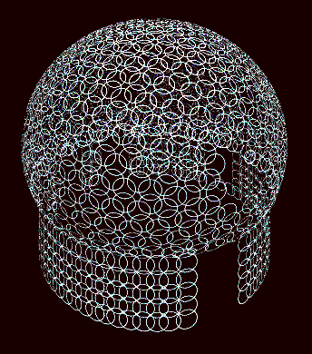
Above: Position of rings used as reinforcement in dome building, (seen from above). The dome was modeled in a minimal size to economically provide for essentials. (The size is about 20 ft. or 6.1 m in diameter). This particular, conceptual approach to building resulted over a 25 year period, of free minded concrete sculpting experimentation, by the author himself. This is a conceptual presentation only. The mentioned sculptural aspect is a specialized building method which emphasizes experimenting with concrete tooling. (For more on this tooling, see links below).
Pre existing ferrocement methods notably use mesh for reinforcement of skin like shells. Mesh implies continuous, fixed linkage between mesh elements. Ringforcement newly proposes "untied" rings as an alternative. Ferrocement depends on the mesh to provide a base on which to apply cement. Ringforcement combines the traditional masonry base of stone and the newly proposed ring, (one nonlinear row at a time) as a base for building up structure. However, Ringforcement uses a much broader selection of graded aggregates than masonry or concrete. These are thoroughly coated with cement paste, as in normal concreting, but rarely the case with masonry. Masonry typically omits intermediate stones from masonry stone size, all the way down to sand particle. Yet it is this continuous grading of aggregate particles which economically improves ultimate strength for cement mixtures. Emphasis on this unusual synergy allows vertical building progress without the slumping tendency of ordinary, freshly mixed concrete and also without the masonry focus of close packed bricks or large faced stones. The mission of Ringforcement is to attempt a new synergy of materials. It is secondarily an attempt to extend aggregate size ranges. Primarily, it is the employment of rings as the choice of reinforcement. The method invites all scales of implementation.
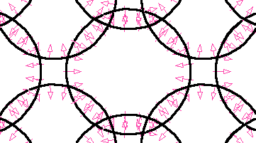
Above: "Compressive Chain", Black rings overlap to create zones which "inter- loop" . Compressive units of embedded concrete bind overlapping rings. The red arrows indicate compression zones for individual rings. The overlap of compression zones, between neighboring rings, results in an extension of tensile strength over the whole of the constructed element.
Linear reinforcement rods are recommended along perimeters and outlines, as in normal concrete practice. The author has found that overlapping rings provide the same strength levels as mesh reinforcement provides. The casual, testing methods used were believed reliable in that mesh tests are generally unofficial, since mesh qualities vary. The testing referred to was breaking up old work by hammer and noticing the relative strength levels. The overlapping of rings in a concrete body, transmits the tensile property of reinforcement steel from one ring to the next. In compound curves, this is significant, since mesh is planar, (that is: it cannot be elastically formed without kinks which cancel the chief tensile property). Compound curves are structurally advantageous, reducing the surface area required to enclose a given space. Through curvature, cost may be reduced, (synergy). Without breaking a budget, sculptural qualities are also possible.
Ringforcement is not restricted to domes exclusively. Compound curves can shape buildings very differently. Walls unrestricted by traditional, rigid box shapes, are hereby build-able using this ringforcement method. A given budget is extended, costs are cut, originality is added, and culture is extended.
Is this new? Compressive linkage for rings is new, only in that the author has not noticed this particular approach published, nor discussed, nor suggested before. Structuring
What are some advantages?
These advantages are available where gravel is minded and labor is willing. Advanced tooling development is a another possibility.
Advantages over concrete are 1) reduced concrete form work, 2) ease of reinforcement placement, 3) less shrinkage during curing 4) unrestricted curvilinear possibilities 5) lighter shell practicalities, 6) use of rawer material, hence savings through local economies, 7) combined monolithic-structure and finish process in one (flowing) step.
Advantages over mesh formed ferrocement include: 1) ease in thorough cement coating of all metal reinforcement surfaces. By contrast, penetration of overlapping meshes of ferrocement is more difficult. 2) Meshes costs more industrial effort to produce. Rings could be efficiently mass produced, or alternatively flat wire spirals offer testing insights. 3) Shipping, and mass handling of rings, rods or wire is simpler than restrictively sized mesh products.
Disadvantages?
This synergy presents several issues which are difficult to implement. Foremost is trying anything which departs from traditional labor practices, E.G.: mixing concrete with unusual aggregates. Traditional equipment does not ideally lend itself to the task. This suggests either extra man hours where labor methods are used. However new experimental equipment concepts are available. (Links below).
A limitation for small crews is the allowable progress with "green" (uncured ) cement. For nearly vertical walls, a single story is possible in one or two days. But sloping beyond several degrees requires additional support. Ringforcement might or might not apply to overhead flooring with an integrated joist- flooring system.
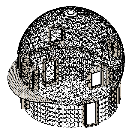
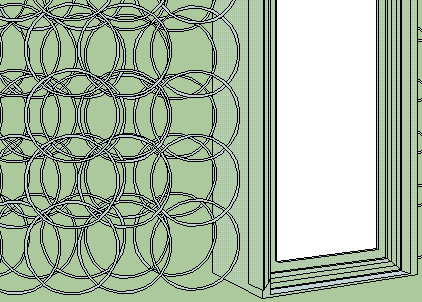
Above: Same CAD dome model shown above. Two sets of rings are shown for two layers of ferro concrete, on the first story wall. The two layers sandwich thermal insulation, which is not shown. The curved dome surface is represented by just one layer of rings in this rendering.
Variations Of Ring Sizes
The paragraphs and pictures above might be mistaken to imply : "one ring size fits all". Rather, multiple sizes of rings are intended for your consideration. Small rings could conceivably replace some of the large aggregate. Certain localities may not have cheap concrete aggregate readily available, substitutes might be explored. An alternative ring design might utilize several ring sizes, or denser coverage of rings. Denser ring coverage (or more rings per unit of area) would call for rings of thinner gage. This idea opens additional exploration of experiments with rings as a more refined replacement for aggregates, indeed graded ring sizes in the manner of concrete aggregates. The efficacy here depends on comparative shipping costs, between steel and stone, which for some areas, could favor the use of greater proportions of rings. Non metallic rings are also a possibility.
A 3D Ring Matrix:__Here is a link to some further developments with cell like reinforcement.
Wall with contoured surface and ringed tessellations is tested.(October 2000).
Pictures of preliminary strength testing during summer of 2000.
Sprayed Monolithic (Balloon Formed) Domes Considered
Admittedly the author has sprayed concrete structures no larger than 12 ft to 4 meters, (using jury rigged small compressor equipment). This much is assumed: House sized spraying requires expensive equipment and is limited by the relatively few form sizes and configurations which are seamed together. Ringforcement as aggregate might adapt to air form spaying.
Materially, the sprayed concrete generally has small aggregate which increases the spray price for a given thickness. Other placements methods can economize on cement paste costs and achieve equal strengths. (This is truer for localities which have gravel mining or benign mineral dumps within reasonable trucking distance).
Pumped Concrete
Concrete pumping is an already existing, widely available service which can be applied to ringforcement. It has a limitation on the size of stone which can be pumped. This size limitation might loose some cost advantages offered by larger stone particles. It might also introduce more difficulties in work scheduling, (in the case of small operations). Structural concrete work always demands intense concentration but is more intense when more than one contractor is needed to coordinate schedules.
Other Materials
The use of plastic, fiberglass or other high tensile strength materials is plausible. Composite materials are a credible application for ringforcement. The essential concept remains the same: high tensile rings combined with low cost compressive "filler" material. The rings are "chained" by compressive linking instead of by tensile continuum. Therefore a new concept of "compressive chaining" is formed. I would love to "extrude" rings directly out of natural or synthetic materials instead of using wire like base materials.
Orbital patterns of physical entities, from sub atomic, on up through molecular bonds, to astronomical orbits, all share annular and steric patterns of existence. Additional principles such as feedback loops and regenerative phenomena also inspire the synergy of ringforcement exploration.