"Reflex Spin Amplifier"
"Spherical Reflex Coil"
"Plasma Resonator"
"Concentric spheres and spirals"..... (History of this page).
Conventional dipoles have long been visualized thus:
Left, above is the traditional electrical dipole as indicated by 2 circles. On Right, is the traditional magnetic dipole, for spherical volumes (said of earth). By comparison, below appears a concentric assembly of 2 spherical surfaces, (tangentially) connected with a smoothed, torus outer-half-section. These objects are called surfaces in geometry, in that no thickness or no volumes are indicated.
Above, one concentric dipole concept is under visualization. The new tool in formZ's latest version (beta) offers live clipping planes, to see cross-sections quickly and dynamically. I love it. However i am still trying to get more complex, spherical objects to perform:
My older models are further below. The next gif animation (of Dec 2012) is based upon a photo named winterbourne-stoke-england.jpg... (The highest resolution i could find at 2880x1800 pixels).... The concepts include my continued internal debates about... The geometric structure of resonators... Incorporating several aspects of helical orthogonality, (described here). Combined with gleanings of the dynamic aether as it was variously developing a 100 years ago.
One Objective: Conceptualized Experimentation: Observe twisting magnetic poles. Except by use of spherical structure instead of cylindrical structure. I actually purchased some silver-conductive epoxy along with some ceramic-nonconductive epoxy from http://www.cotronics.com... My planned method of construction was to start with a hollow spherical chamber for a center. Paint on the first layer of silver-conductive epoxy, with one pole 'hole'. Then follow that with one layer of non-conductive ceramic epoxy, leaving just a rim portion exposed. Followed by continuous painting from the said exposed ring, of the second layer of silver epoxy. Followed again by the non-conductive layer. Repeating this sequence to produce many layers. Although i could only afford a few layers at that point in time. I never could afford a decent amount of materials or equipment... Besides i was debating with myself: just how to add a magnetically conductive layer between each electrically conductive layer. I was debating how to make one layer exclusively-electrical and the other exclusively-magnetic. At the same time make the magnetic layer insulating to electricity, but also capacitive. Thoughts of using fast drying, electrically-insulating paints did nag at me. Furthermore embedding iron or other magnetic powders in this 'paint', does seem logical. The debate in my head lingered. The duties of life called my attention elsewhere.... By the time i wanted to actually start, the special epoxies had turned pasty- Too hard to apply in a thin coat or mix up part A+part B, (normal epoxy procedures)
. 
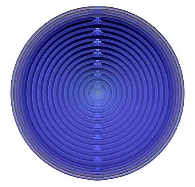
More Turns = Lower Frequency

I never trusted the patent process for small individuals like me. Nor any of the patent-helper companies who promise to work with small inventors. At some later point, i saw these efforts as a way to get killed by the power-possessing beings, who haunt planet earth. A creative-thinker can live much longer by staying a poor nobody, literally. Psychopaths and sociopaths literally dominate all commerce in tidy little controlled economies, punctuated by wars of convenience. Let us suffer for art and for cosmic creativity.
8 Layered Spiraling Sphere Modeled With Arcs
A Continuing Study By
Bo Atkinson
3D CAD work began 1993 with SilverScreenTM Software (later
exported to formZ)
Models on this page can
be viewed as flat spirals which are rotated on or near a polar
axis to describe skins. By adding thickness, useful experiments
in physics may go beyond ordinary electromagnetic induction.
This skin was made from the
basic flat spiral which
was then copied and rotated
10 degrees on (undrawn) axis
which passes through the
sharp connecting points.
The resulting pair of
spiral lines were then
"skinned".
The black and white wire frame graphic
above, is now rendered with
semi-transparent skin to
enhance visualization.
Here the skinned spire
is further
rotate- copied.
This is a partial,
"concentric, spiraling sphere".
On left is sort of an xray of the
full concentric, spiraling sphere.
A much narrower angle of
perspective was used than above
in the partial version.
next
Here a single section as in
the first graphic, has been
"unfolded". The long shapes are
flattened out to better show
their pattern.
Here is one half of the cross section. -->
Below is a bigger JPEG,
offering a clearer picture. A black line drawing similar to
the one on the right has been superimposed to delineate
the cross section profile. Also
 Below: The "spiraling sphere"
above has been adapted as as an electrical inductor, hence "spinductor".
The shell like structure above, is used as an electrical conductor.
Other adaptations are also under consideration.
Below: The "spiraling sphere"
above has been adapted as as an electrical inductor, hence "spinductor".
The shell like structure above, is used as an electrical conductor.
Other adaptations are also under consideration.
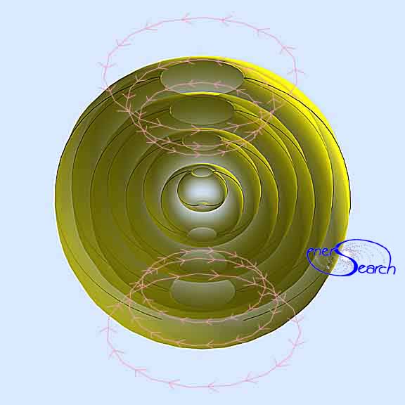
The "polar" openings at top and bottom of this graphic may be enlarged by
use of conical spirals in the 3D model. Conversely, the polar holes may be
essentially closed by use of a flat spiral in the 3D model. This concept
grew from my childhood speculation: If an electromagnet could be spun fast enough,
would i see light? (What children think of!).
As an alternative experiment, the electrical and magnetic fields may trade places.
In this new experiment, the red and blue symbols are regarded as electric current,
which travels in an electrical coil.(A graphic diagram will be placed here, when i
find time to do this).. The yellow arrow-ed path becomes the magnetic path,(during one
electrical pulsing of coil). I suggest the name "retro-ductor" for this
experiment, since the magnetic field is forced up and down longitudinally.
Click here for more inductive concepts rendered via CAD (306 KB !)
During the 80's and 90's i made various efforts to build different inductor
experiments which utilize the electromagnetic fields mentioned here. (These
experiments continue, at some point i will post them in detail at this site).
If i had the chance i would like to adapt these geometries to plasma experiments
and also to discussions in cosmology. (Here is one example of one
attempt to apply bi-axial geometric concepts to cosmology).
Click here to see "hyper" spiraling, concentric spheres.
Tetrahelix As Prism, Light/ Ray Tracing Experiment
Tetrahedron used as a mold to model a "poloidal" biaxial structure.
Ringforcement
The content on this website, http://harmoniouspalette.com, is placed in the public domain only as a free exchange of ideas and as a "hard studied wish to serve life". The author assumes no responsibility for the improper use of the concepts in these web pages, as all relevant laws of life and local codes should be verified and observed before any building or experimentation proceeds. discussion is welcome, please write. Bo Atkinson
History of this page: This page visualizes dipole field configurations, in varied aspects. This page was started in 1996 on agate.net, later moved to midcoast.com and now rests here at harmoniouspalette.com. As an artist, builder and 3D modeler, my effort is to visualize physical structure in 3D volumes and also, as 3D surfaces. (In geometry surfaces means no volume and only surfaces area. Volume implies measurable material content). Modeling curved thickness is a challenge for (affordable) CAD software. Therefore my visualizations explore 'surfaces' and 'volumes' as if these could be thin shells or thicker shells.
From my study of electronics in 1975, (Cleveland Institute of Electronics, a mail order study course, but without the expensive lab module of that time)... and my study of 3D modeling beginning in 1994, gave me ample tools to visualize the concepts presented here. I began using a powerful 3D software named formZ in 1995.
As a sculptor in the 1980s, i experimented with building coils seen here. I was isolated from the world, making a laborer's living in the woods of Maine. I could afford very little of the alternative science publications. I was not conversant with conventional academic sciences, nor did the popular theories make very much sense to me. Alternative theories made more sense, from my very limited access to publications.
This update continues my artwork-upgrading while leaving intact the images from earlier times. Earlier work was done with weaker software versions and weaker internet conventions of decades past. However, currently i have no time to update my web-coding skills, nor incentive for that effort. All creativity and conceptualizations were placed in to the The content on this website, http://harmoniouspalette.com, is placed in the public domain only as a free exchange of ideas and as a "hard studied wish to serve life". The author assumes no responsibility for the improper use of the concepts in these web pages. All relevant laws of life and local codes should be verified and observed before any building or experimentation proceeds. discussion is welcome, please write. Bo Atkinson, on fair use basis. So that according to law, this work has not-been-elegible for US patents . Earlier web addresses used wer: midcoast.com/~bo and agate.net/~insearch.
-
Email comments welcome 
Bo Atkinson's artwork index.html