Bo Atkinson's Blog page ~ ...Bo's pictorial index spanning over 2 decades.
December 2016 ~~~ My Latest Electromagnetic Research On A Radical Radial Pole Coil
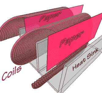
April 2013 Envisaging Transverse Force Fields: An ordinary coil-of copper wire was slotted into a scrap piece of finned heat sink, (in photo below). Assessment of transverse magnetic field patterns is aided by the fins and paper strips. Following further below, my text refers to models generated in in professional 3D architectural software, (using formZ 7.1).
![]()
Each fin holds one full turn of the ordinary coil. Next, paper strips were inserted to divide each full turn. Thus, the vector forces could be more easily visualized for each half turn. If we visualize the wire's force field, symbolized by the blue arrows, we may consider the nearby force vectors, (lighter blue).
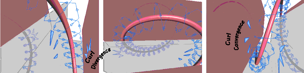
The paper and heat sink fins-only, can be imagined as plates or strips of an electromagnetic core material. The polarities will be opposed, but in an unusual manner.
___________________
Ultimately, many individual, parallel coils are to be laminated. This transverse-deflection is the main concept discussed on this page. It has inspired the configurations presented further below. It serves as my postulate to build prototypes, in due course. The unusual field character provides me the spark needed for action.
__________________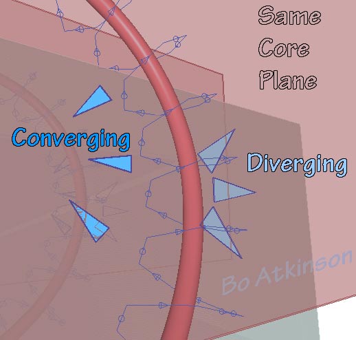
The convergence and divergence, within close proximity to the drawn plane, deserves further investigation. I have wondered if the term "transverse induction" might apply. However the the term "Transverse Force Fields" may be more conservative- Given that something other than inductance may yet transpire. Singular core strip might prove more interesting. Or possibly two or more strips all together may prove more interesting, (like laminated cores to reduce eddy currents). Or instead of core strips, amalgamated coatings might prove more interesting. Coatings can fill up the pie-shaped nature of the radial arrangements.
![]()
Until this paragraph, observation of the half-turn core division, has been considered. The strips and fins help the study. We see that simple strips when inserted, will be confined by the coil wire. Yet experiments should also test the effect of extending the plane of the strips beyond this confinement. (This 'extending' aspect is illustrated further below). The core options branch out with multiple configuration applications. I will present some of my application ideas on this web page.

Parallel coils may confine coil material along the plane of the lamination faces. Numerable applications for these principles, will follow, below and on other linked pages. I have some methods planned to assemble these and other laminated coils. Diverse principles might be applied differently, in case experiments provide multiple effects. Methods for using printed circuit subdivisions might prove useful. Various configurations and different manufactured materials will be tried to explore further ramifications. The following models provide accurate geometry tests. Further below, additional examples will reveal related thought experiments. (Magnetically coated wires are presented on this linked page).
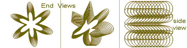
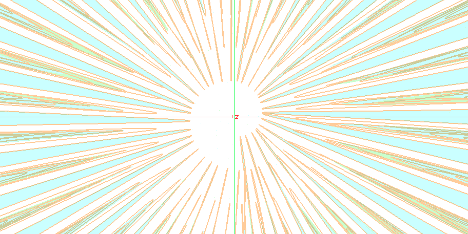
The preliminary purpose is to envisage transverse field effects. The blue arrows above, crudely represent 'expanding' and 'contracting' arced fronts of magnetic force, along copper paths. This field effect is expected by use of multiple, ganged, parallel coil paths. These paths are conceived both as insulated wires and/or as shaped sheets. My software and hardware are limited. So the field depictions are also limited. The next image below visualizes corresponding views of 12 toroid coils, which are ganged together along a row.
 Same Model!
The animated image below flies around a single, simplified, stretched toroid. I expect FEA software (finite element analysis) would verify my postulated force fields, as modeled above.
Multiple "ganged toroidal sections" could make up, a transverse multi core laminations. Higher inductance may be had, to accommodate higher voltage, with longer wire windings. Traded off inductance value is expected to yield effects, as yet to be charted. The next 3D model illustrates plate-like sections of multiple-cores. Coil turn count is limited in these models to reduce bandwidth of web images.
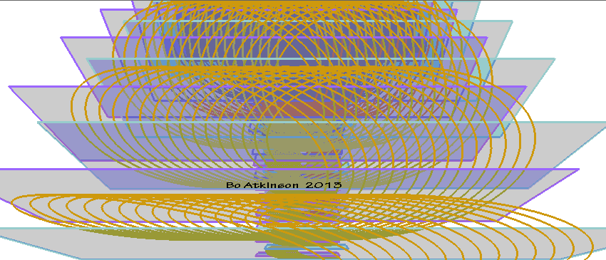
The axially-polarized, multi-cored, alternating-polarities are indicated by purple and blue rectangular 'plates'. (Further experimentation may incorporate wedge like cross section to fill all space.) Introduction of chief concepts, continue below with a view of this 3D model, zoomed out to full view.
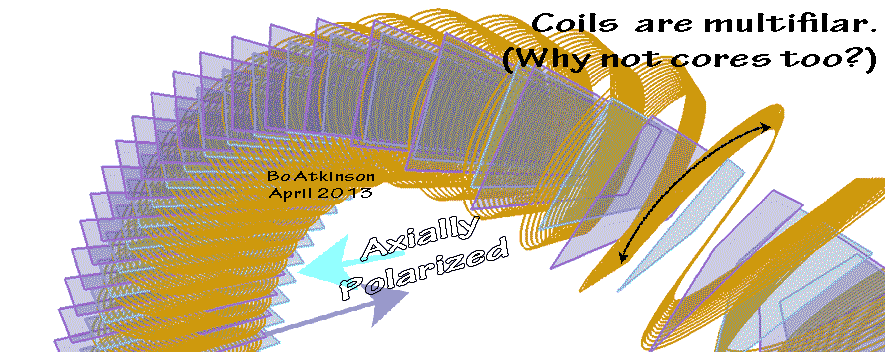
The next picture below contemplates rounding the core plate edges, (for edges which may protrude). While the opposite end is confined by the electrical coils. It is notable that the confinement inverts, for each polarity.
![]()
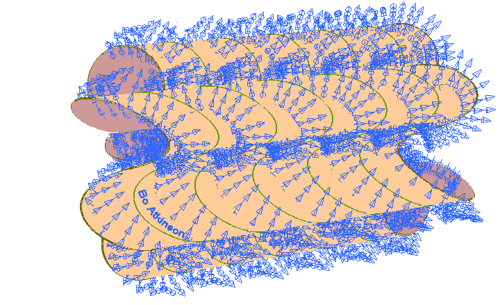
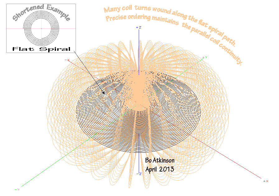
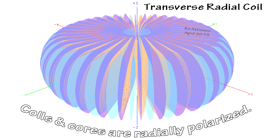
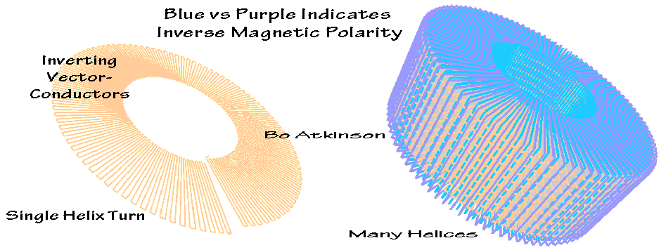
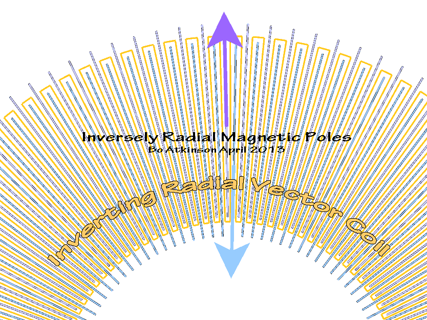
The consecutive, parallel coiling in the models above, proceeds along the "donut axis". The next model demonstrates that the coiling can otherwise proceed 'radially', instead of 'axially'.
Note that these windings bias the convergence and divergence at the far ends (of the drawn core planes).
Next below, the xyz axes have been hidden. Also there is a translucent greenish backing for the coils in image above. This has been removed below. Such efforts are part of the visualizing technique.
Next below is a stack of the radially polarized models. I'm doubtful that combining both the radial and the axial polarizations could work out . Due to the physical confinement problem, of clashing electrical and magnetic planes. There could be test case for dipping coils in coatings first (and then potting the combined coils), however. One reason to search along these lines is the lure of finding configurations which increase self capacitance. Stacking the radial coils:
![]()
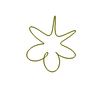
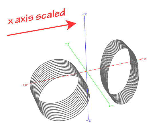
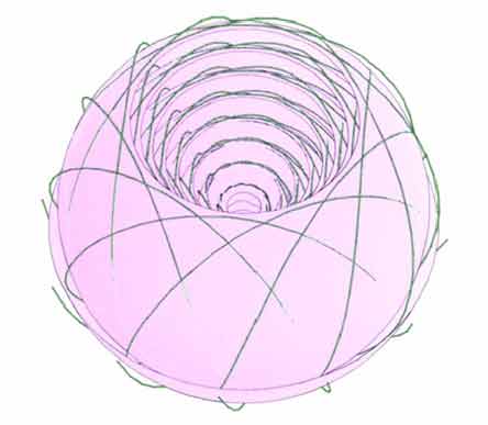
The radial transversal was generated by means of routing a regular helix form upon a scaled helix form. In other words one helix upon another helix. The image below displays a close up view, of the coil center. The spiral path is evident. (The green-red cross is the xyz axes).
Coil turn count has been limited in these models to reduce bandwidth of web images. The fully circular aspect of the coil turns does however result in the far end of the cores having just one set of windings. Testing this aspect is one objective.
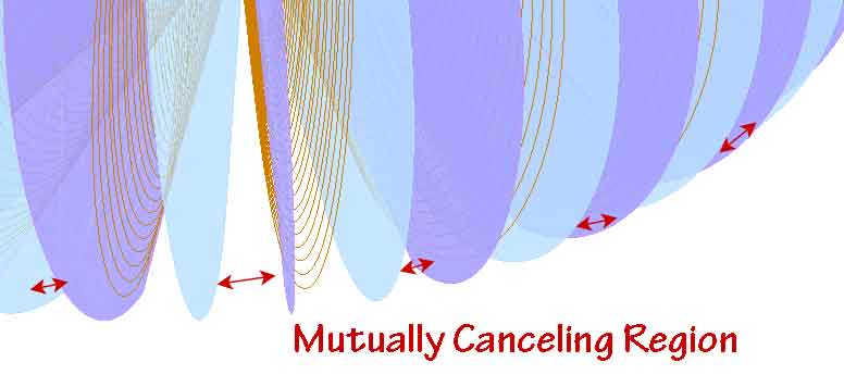
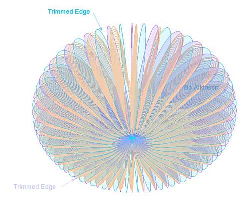
Regarding strictly the simplified versions, exactly as drawn, i expect that the end regions of the cores, will have a mutually cancelling effect-- As a result of the half turn, lacking the other half turn in between, in the vacant spaces indicated by the red arrows. This might in itself deserves inspection. Yet there are remedies available to reduce the emptiness effect. One, partial remedy would be to scale windings along the x-axis only. This feature has not been included in these schematic drawings:
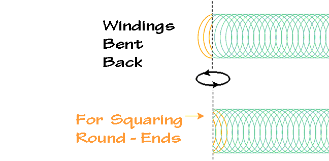
For complete winding coverage, over the expanse of the core-surfaces, (in next image), illustrates a method for bending windings. This feature can actually be done fairly easily in real life. However adding this feature to these models is omitted, here. An important note: This bending axis, (dashed line), will be at the ends of each core-- in case increased inductance is sought for.
(Later Addition RE: Sheathed Cores) The next picture below illustrates use of sheet like cores. Transverse radial cores and coils, might be prototyped by use of magnetic-core-coatings. (in that sheets are difficult to shape with needed precision). The sheet material has been rendered (imaged), semi transparently, to improve the visualization. The spacing or separating of the cores, (in image below), only emphasizes two polarized cores and one,contiguous, matching, coil configuration.
![]()
My first 3D CAD explorations of flat spiral rings is on this linked page.
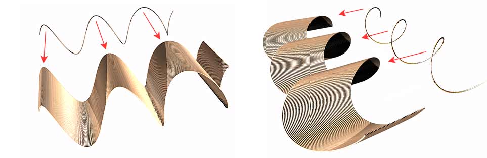
Besides flat spiral coils..... Yet another generalized model with a further aspect to consider, is the case of sharper-cornered, faceted 'windings'. (My software contrasts faceted and smooth geometry, which helps the schematic modeling exploration greatly). Next below was my excursion into sharply cornered vectors, (instead of rounded helices). The initial purpose of this experiment would be to investigate for a difference of real life effects:
Does the helical, rounded coil version manifest different effects from the straightened vector coil? Off hand, i see reduction of unwanted eddy effects in the multi cores of both implementations. There seem to be magnetic pole-subdivisions in both configurations. The straight and sharply cornered paths, of the vector-conductors, lend more, i think, to emission effects. I tend to expect differing observations.
Regarding Prototyping: I also expect to find the rounded coil building to be easier than straightening the wires to build the vector coil. However, building experiments, as a art in itself, may result in discovering new configurations.
Here is prior art form, incorporating various radial arrangements of "flower coils":
This page has yet to considered a self capacitance enhancement. Configurations for increased self capacitance of windings will next be suggested. The generalized toroidal configurations of these coils can implement the Tesla concept of interleaving distant segments, of the same coil. The "donut hole" provides closest connection points. Or, a continuous, uncut wire might "step through" adjacent 'laminations', as "laminated turns. This can provide room for crossing connections.
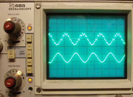
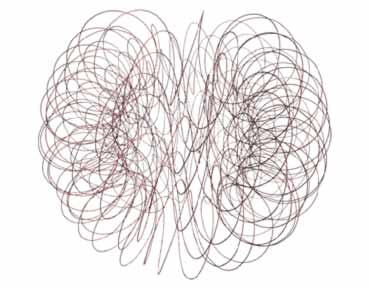
The oscilloscope-photo shows my typical harmonics achieved with older, cruder coils, which bear some aspect of transverse induction. I have wondered if frequency harmonics (from swirled or swerved magnetic fields) could become significant frequency multipliers. (Achieved with coils alone, without external circuitry ). The rounded paths lend more to my postulate of frequency transforming effects. At this writing ,the fullest implementations of transverse winding configurations, have yet to built and tested. My focus so far has been primarily geometric modeling. Conceptual modeling clarifies efficient probabilities, where some of my models are challenging to build with my humble tooling. My goals can be set with the limited apparatus and equipment which i possess. Here are other pages of this series of webpages, which focus on transverse force fields:
InductiveCouplingGeometry.html
Reflex-Vortex-Interleaved.html
HelicalWaveTransverseCoil.html
Conceptual artist is targeted, for modeling coil art?
![]()
These modeling images are work-mode-displayed, (meaning quickly rendered and schematic in style). This allows quick view-navigation with good accuracy regarding clearances, between elements.
~~~~~~~~~~
I get side tracked with life's needs. So that i never devote undivided, focussed attention to my coil building experiments. It is stimulating to see others making progress with free energy. I found these "web devices" offered through a (once existing) website: http://freeenergynews.com
Mig welding wire is stiff and coils nicely by use of a drill.
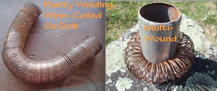
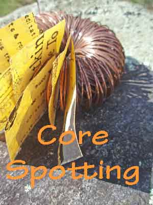
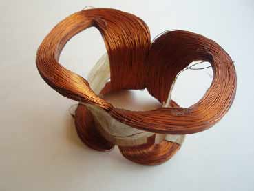
A quick test for methods to wind up a transverse radial coil. The test confirms that the turns do self-group to some extent. Though this test was using springy steel welding wire. This welding wire is stiff as compared to copper magnet wire. Spotting where each successive 'parallel' turn belonged,went well.
One of my handiest methods for coiling wire is to use a drill rigged with tubing:
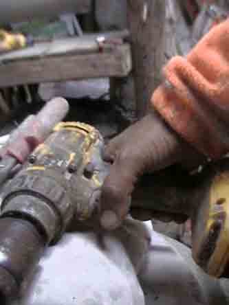
A light-weight cordless drill with a large chuck makes a good coil winder tool, (half inch or one centimeter chuck opening.)
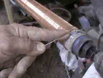
A suitable pipe of about 1 inch or 2 centimeters was firmly fitted over a "hole-saw". A rigid type of hole-saw is used, (Half inch chuck and bit). A firm fit (and saw-tooth protection) were provided for, by wrapping plastic tape over the hole-saw. For long term use tack-welding or other means can also be used to secure the pipe to the drill. Variable drill speed allows one to learn and practice.
~~~~~~~~~~
A deflection coil from an older TV, actually bent the windings to diverge the beam, across the screen:
Pictorial Portfolio: http://harmoniouspalette.com
Note: My 100s of pages on this website, http://harmoniouspalette.com, are placed in the The content on this website, http://harmoniouspalette.com, is placed in the public domain only as a free exchange of ideas and as a "hard studied wish to serve life". The author assumes no responsibility for the improper use of the concepts in these web pages. All relevant laws of life and local codes should be verified and observed before any building or experimentation proceeds. discussion is welcome, please write. Bo Atkinson and are furnished "as is" and "open source". My creativity is posted as a free exchange of ideas and as my "service to others". Caution: The author assumes no responsibility for the improper use or improper misuse of the concepts in these web pages. All relevant laws of all kinds and local codes should be verified and observed before any building or experimentation proceeds.
For customized work, i offer great modeling skills and professional software licence at a laborer's rate. Here is my Design~Build Consulting Page: http://harmoniouspalette.com/services.html
![]()
Note: The content on this website, http://harmoniouspalette.com, is placed in the public domain only as a free exchange of ideas and as a "hard studied wish to serve life". The author assumes no responsibility for the improper use of the concepts in these web pages. All relevant laws of life and local codes should be verified and observed before any building or experimentation proceeds. discussion is welcome, please write. Bo Atkinson