...
December 2016 ~~~ My Latest Electromagnetic Research On A Radical Radial Pole Coil
This 2015 link elaborates my spherical vortex rationales and some construction methods.
(Originally a 2012 page?) This page reviews some conceptsof force field induction by visualizing a variety of non-linear geometries. Rather than analyze mathematical numerics, this page visualizes structurally related geometries of induction. (Images of geometric models are my work, unless otherwise noted). My geometric models date back to the 1990s and explore helical and spherical configurations. Although my use of terms like helical and and ring vary in definitions. Ring arrays below can represent contiguous, flattened coils and then be mapped to spheres below.
These concepts simultaneously explore universe mechanisms as well as imagined approaches to buildable and functional models. Ordinary coils were also "texture mapped" to polygonal surfaces. My helical visualizations have always bridged multiple purposes, e.g.: bridging applications from housing to inductive fields. Below is a random example of wrapping helices or EMR coils around multi-axial paths. My built experiments like coils above are here.
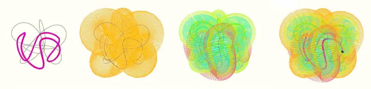
(My geometric modeling of the above image started here.) Helical geometries have always inspired me-- Could such concepts apply to physics or to practical devices or to architecture or to spiritual dynamics or to life ? Could the geometry represent one energy type or another energy type? Could the geometry represent an electrical conductor or amagnetic core? Could traditional indoctrination inhibit a structural cognition? Could conventional notions of energy miss the better interpretations of nature? I explored various geometries which might provide orthogonal path relationships-- Paths which might be used interchangeably as conductive or magnetic fields.
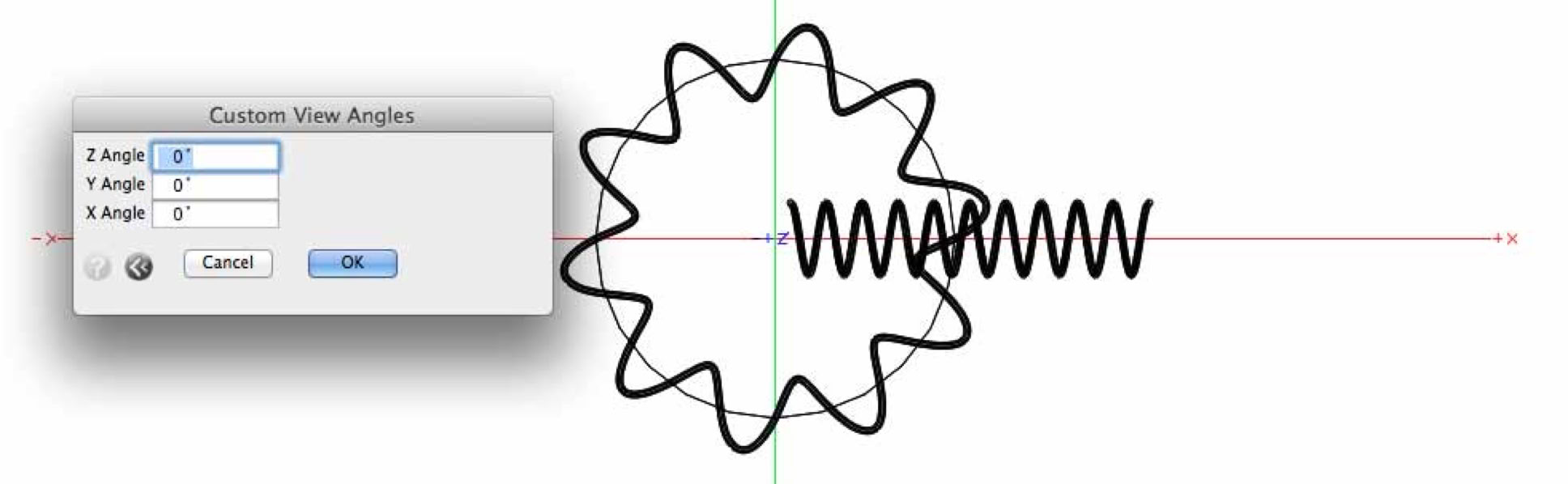
I had stumbled on a particular, anomalous symmetry with complex coils. But upon verifying, discovered this particular anomaly was also to be found in ordinary coils. I began to wonder if the anomaly might apply to coil energetics. Could this deserve further exploration? I explored a wide assortment of unusually coiled geometry, without fixating on conclusions. Let me first start with a simplecoil to explain my anomaly of interest. The geometric anomaly is evident on well spaced, ordinary coil turns.
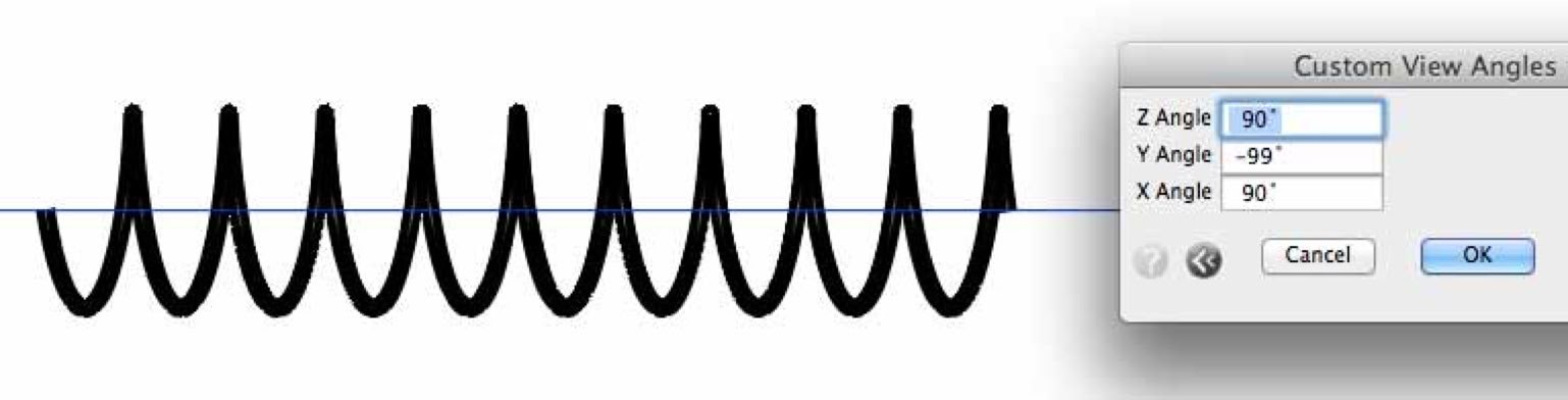
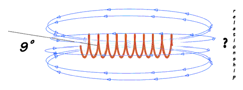
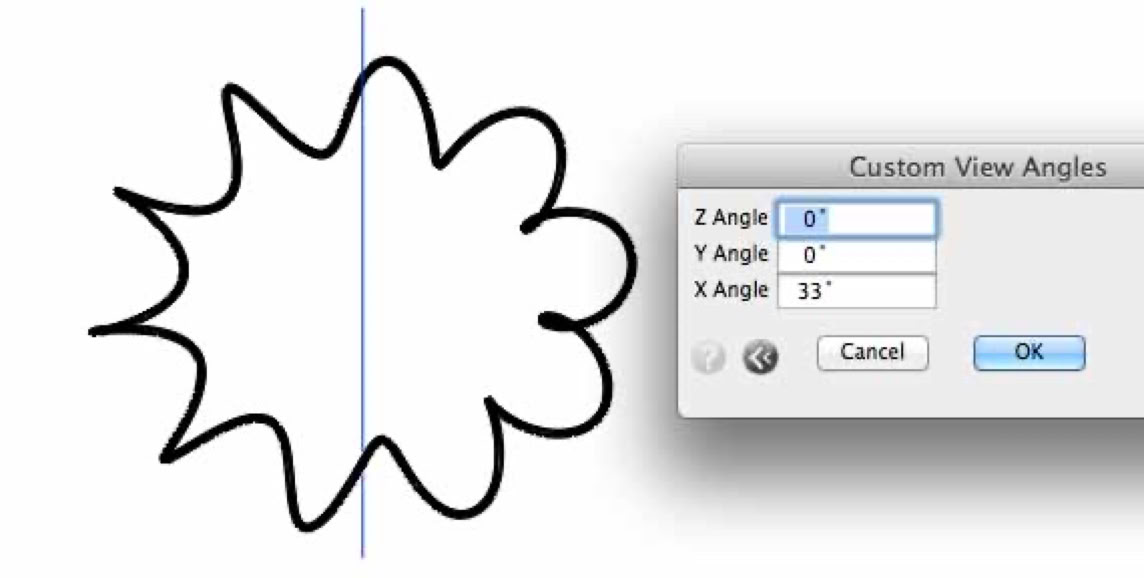
This imbalanced-symmetry is revealed, only when viewed at particular angles. Angle as in turning a coil (or small spring) just 9 degrees in the figure above. (Separately, a perspective view angle of "0 degrees" best reveals the anomaly For more about perspective-view aspects, see here.) I wondered if the "unsymmetrical profile" (as in the spiral model above), might somehow relate to energy fields. If so, how so? Something like a turbine effect or a wind milleffect flashed in my mind.... The blue line precisely represents the simple, spiral coil axis. If we compared 'areas' as divided by the coil- axis line-- Then one side of the axis has more area than the other. Hence, could that somehow translate into an effective, but as-yet-unexplored turbine effect? What sort of flow could engage this aspect? How would such a flow be engaged?How would the coil be aimed?
Is it simply a geometric aspect of the already documented magnetic field lines? Where the Custom View Angle and the coil spacing are related tothe coil diameter, thus revealing an symmetry.
Will another sort of energy flow interact or be tapped? Could one corroborate a directional flow which matched the view angle of a simple coil model like the coil above or the coil below? It seems like a worthy investigation. I will compare simple coils first. Densely packed windings might arguably lack the effects of this anomaly.
The two simple coils presented so far have differing coil-axis relationships. The ratio of coil and turn diameters to the spacing between turns,is the key. Additional axis-attributes might also apply. Also, fewer, well spaced turns tends to improve higher frequency resonances-- Will this anomaly help generate power or provide insights? I have dared to wonder.
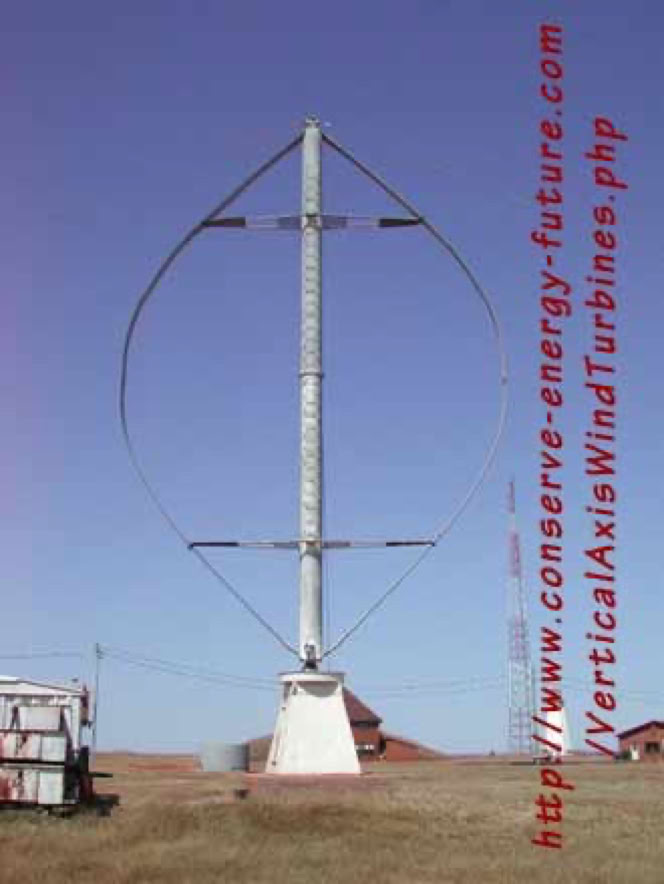
However, we can view google/images for the term "vertical wind mill" (all in closed quotes). Thousands of images come up, many of which suggest that the "wind blades" can indeed employ aspects of helical geometry. Yet there is more to the geometry to consider. Likethe "custom view angles" shown above-- The essence of this view angle might be incorporated to an advantage. Yet aerodynamics is mentioned here, only to show that there is some sort of flow dynamics, already employing plain sections of the helix. Flow dynamics might be key, but a flow of _______?(Is still my question). What might it be named, when and if it is discovered? How will the flow manifest? Would it be a secondary effect? Would the causative force align or correspond in any manner to the mentioned anomaly? A funny name comes to mind: 'fanomaly'. (To use the windmill effect, or 'fan' metaphor).
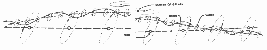
Buckminster Fuller (of geodesic fame) provided the above-scanned-image, in his book Synergetics. It has suggested to me yet another concept which might correspond tothese flow dynamics. The image above asserts the obvious spin dynamics within a galaxy.It can also suggest that if a universal flow of nature emanated outside of the galaxy, then tapping it's effects might involve some process like unwinding or untangling the sought-after alignments. Perhaps, in some way to induce some force. Ultimately can such force be configured to induce EMR?
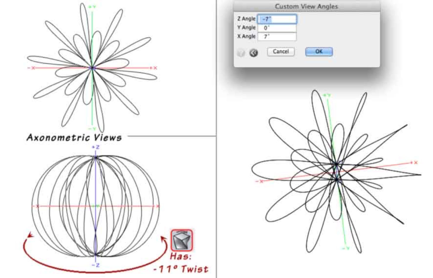
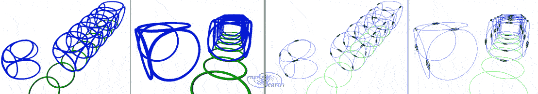
Above modeled coils are shown together: The symmetry -profile is equal, with zero-view-angle. (Axonometric, or without a custom view angle). The toroidal coil is wound around the circle. The circle is centered on the z axis. The spring like coil is wound about the x-axis. The fun in geometry software is merely adjusting parameters:
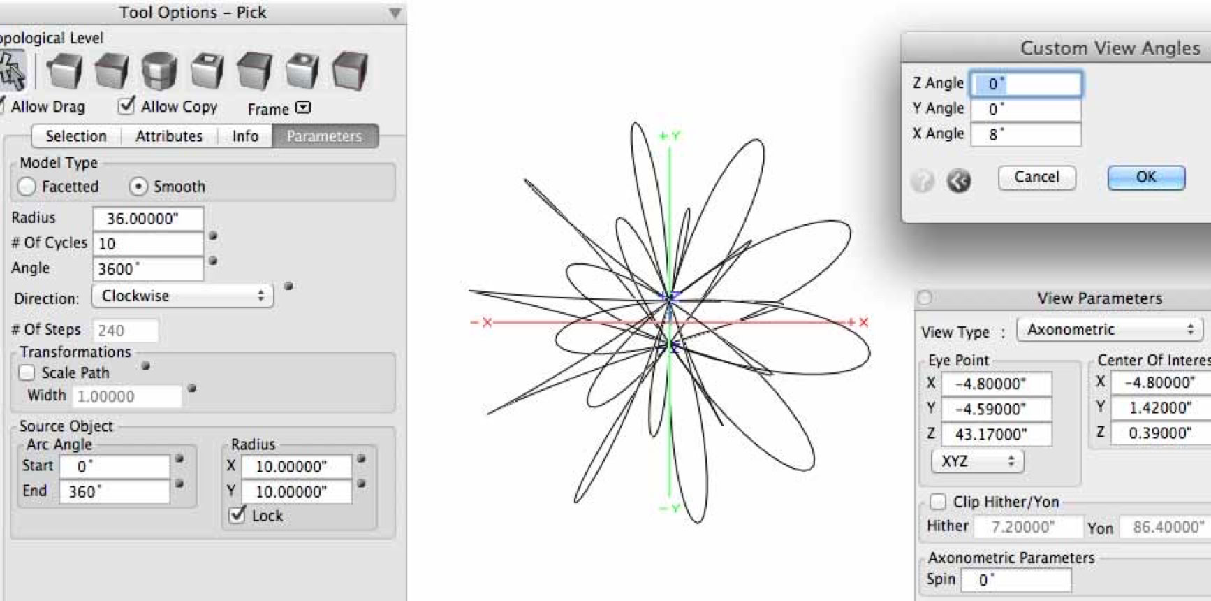
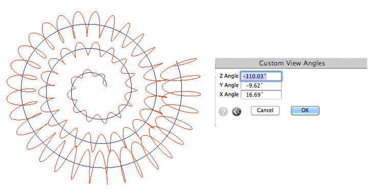
Next above is the same toroid,modified with an unusual parameter: The radius of the of the modified torus winding is larger than the radius of the toroidal path. While the view angle is just 8º (degrees) off of z axis alignment. These relative parameters are critical to the concept under discussion here. Next is a closer look:
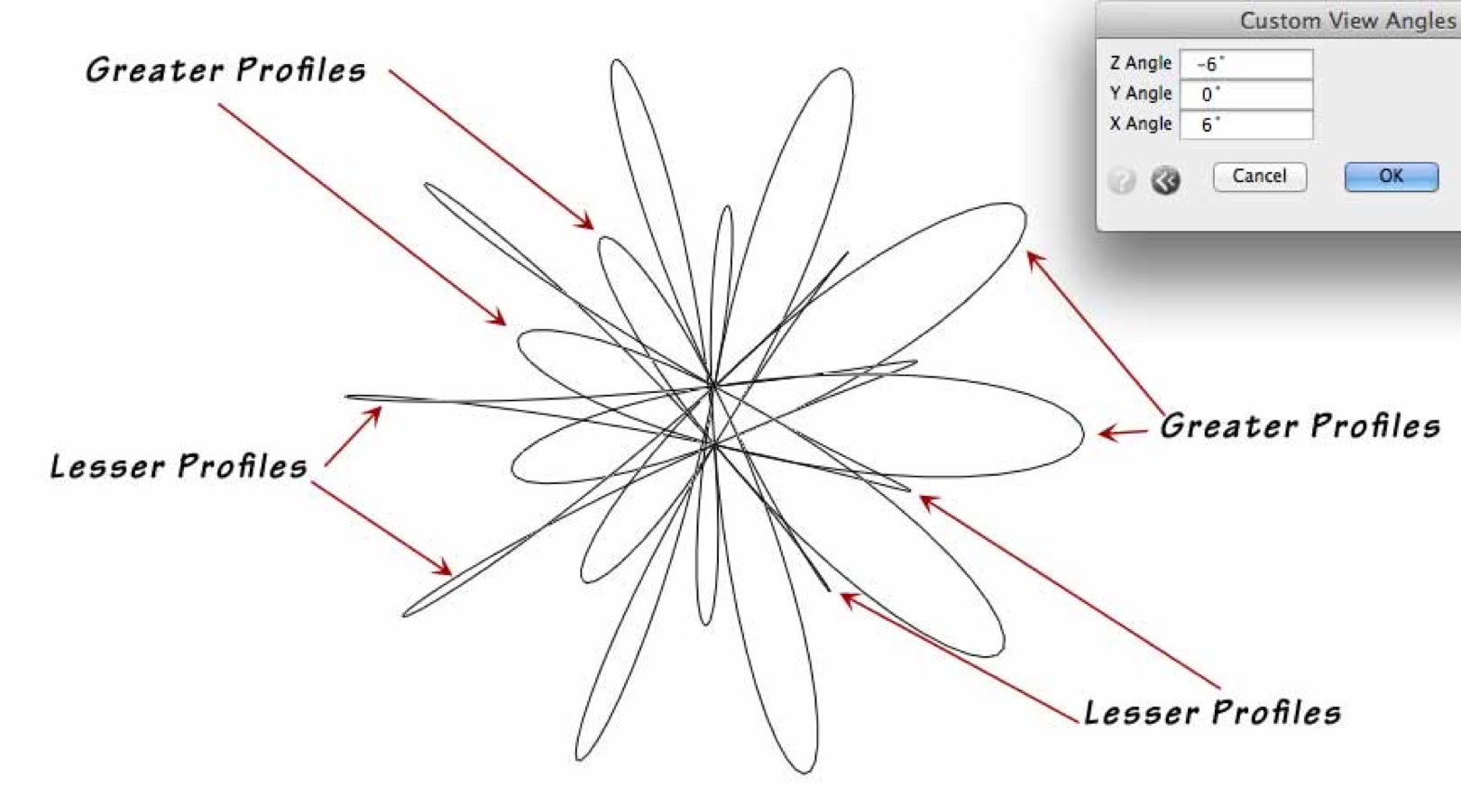
This particular helix or modified toroid seems to possess opposed profile anomalies, within the same, basic helix model. It is based upon the ordinary parameters or mathematical formula, as all helices-wound-upon a circle-path. I decided to generally name this sort of toroid a vesica pieces coil. My additional reasoning about this vesica -pices -namingis linked here. Next is the same model .(Picture is blurred to conserve bandwidth). The geometric edit below was simply to twist the vesica piscis model by -11 degrees on the xy plane. Notice that all the lesser profiles are on one end of the x axis. While all the greater profiles are now on the other end of the x axis.
The point of that exercise was to show that, through geometric editing, one can categorically arrange the like-profiles to opposite sides. Again, the objective would be to search for some sort of practical effect, which is based on profile anomalies. Note that this object no longer fits the common helix formula. There are plenty of ways to modify coils and tori to adjust the profile-anomalies. Generally, the view angle is somewhat close to orthogonal, relative to the coil's magnetic axis. Next is yet another sort of geometric edit, along with directional arrows. After all, directionality should be meditated on.
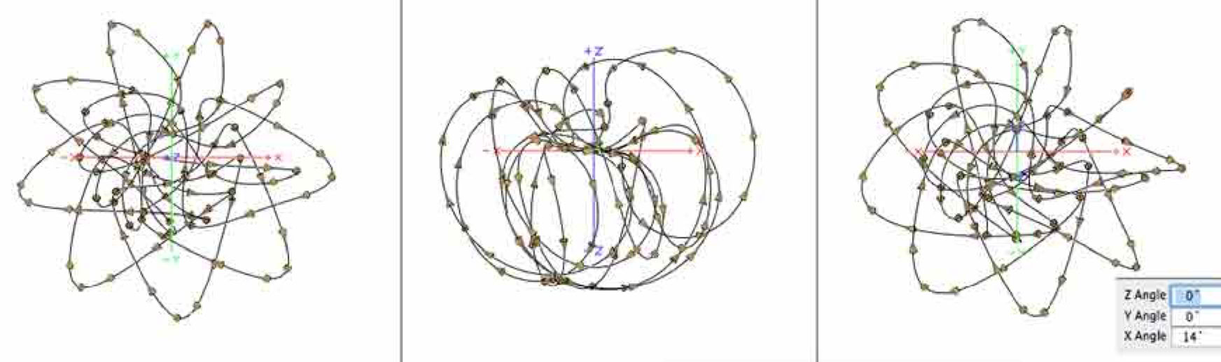
Image above: The left display is the 'Top' view, (no perspective). The center display is the front view,( no-perspective). The model display on the right reveals a sought-for, profile-imbalance. I have wondered if this suggests that recursively wound helices, actually do have usable technological implications. Should the critical attribute be named ? Let us wind a blue helix around the ordinary-spring-like helix, (of an earlier model above).
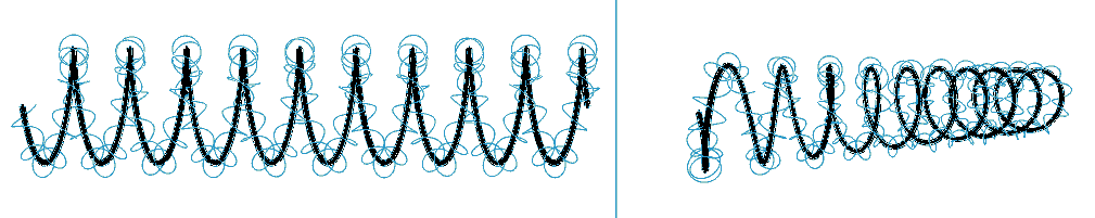
Here we show the same view angle as above, displayed on the left, (with no perspective). One significance of this view on the left is that the blue helix also bears an imbalanced profile. Though this particular imbalance occurs only at specific points along the source-path. The flat-projection of the blue helix reveals helical orthogonality. Could this correspond to magnetic lines of force or EMR patterns? Are magnetic 'lines' independent circles distributed along a conductor wire? Or could these force fields actually be helical in nature?To the right is displayed a perspective view of same model, to verify the ordinary spring-like model. I applied this helical orthogonality inter changeably in coil winding:
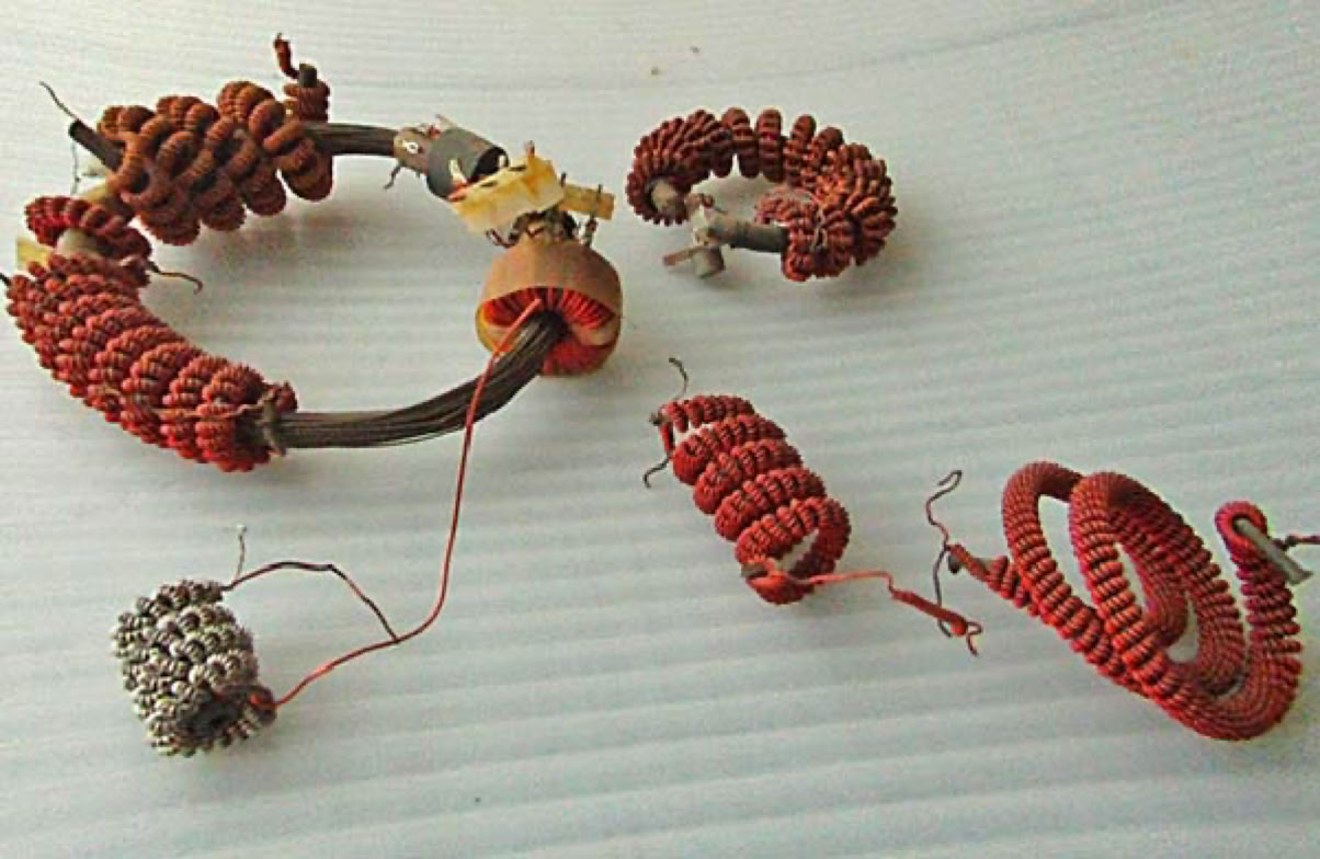
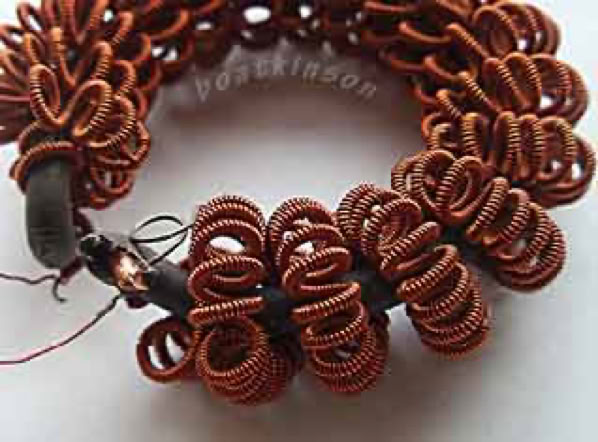
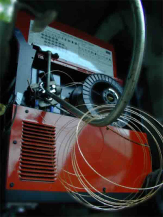
The bottom left coil in photo-above, has a nickle metal wire, which is ferromagnetic, wound around copper... Some coils in the top right assembly show recursive winding relationships. Physical variations have been tried. Like copper wound on ferromagnetic wire, wound again on copper, wound again on ferromagnetic wires in parallel. My own work was with very weak signal inputs, which were "frequency swept" tosearch for the most common reaction, which induced harmonic frequencies (or frequency multiplication) in the pickup coils. Low frequencies were used to accommodate the ferromagnetic 'cores', (which were windings in themselves). Later i will show my efforts with higher frequency-cores like ferrites. (Other descriptive come to mind: "recursively orbital", "exponentially orbital", "reciprocally orbital".)
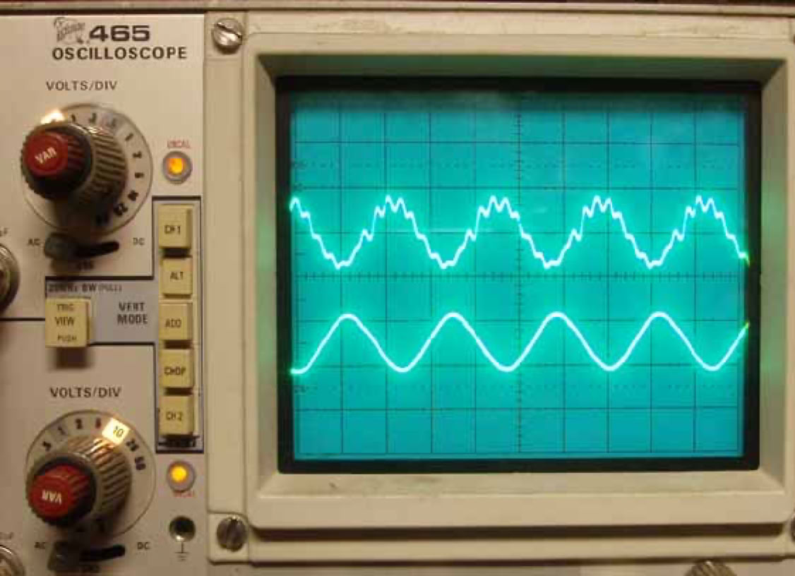
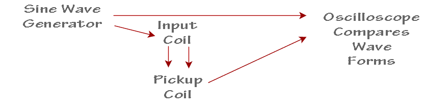
Feeble harmonics are commonly found when multi-axial coils are feebly energized with plain sine waves. I think it is was nearly 1990 when i had bought this surplus oscilloscope, but the picture above was taken April, 2013... Digital imaging for the public was not possible until many years past my coil work. I'm finally getting back to energizing the older coils and got a picture of the harmonic display. To update my web postings on coil explorations.
In 1992 i got my first PC (a 486 with DOS5 & Windows3.1) It took me a couple of years to acquire and learn 3D CAD software,( self trained and low budgeted). Coil visualization fascinated me and suddenly i had tools to explore new aspects of coils and combinations of helicity. Next is a graphic to show my meager attempts to "geometrically weigh" the imbalance of profile: I first tried to use vector based geometry but ended upconcluding that only raster or bit-mapped images could render the wanted profiles. However, my tracing software used to generate vector based software was lost through hardware and OS changes.So i gave up that minor aspect. I'm tired of relearning new software and paying for it. Then loosing it a few years later. I did verify the imbalances numerically, which did suggest that my assumptions of profile imbalance are valid, (geometrically measured).
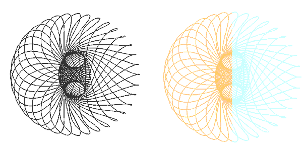
This particular model used many closed curves rotated around a common axis. Instead of a continuous spiral object. An explanation is on this page.
&
Another very old 'poloidal' page is here.
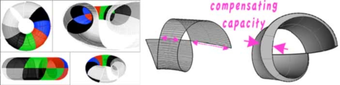
Bending of wire inevitably stresses the cross sectional shape.This is easily verified when bending tubing: There is a measurable distortion.More interesting to me is the natural gap formed when winding a torus-coil. The inner wires may nearly touch, (insulation touching insulation). While the outer part of the wire turns will be spatially apart, (with a gap between). So that, an experimental wire would be interesting to fabricate: Such as the picture below. Which suggests that the cross sectional area of the 'wire' (or wire as a 3D ribbon shape) should always have an equal, cross-sectional area. So that conductors and even wound magnetic cores can have equal cross sectional capacity, all along it's path.
Stacked pancake coils can be arranged to produce reversing radial magnetic fields-- Closer radial-spacing of wires, but distance between pancakes, would strengthen the indicated fields. I found magnetically coated wires localizes the field characteristics per section of wire. Mutual inductance between radial turns can be isolated, where the lateral-radial turns bear opposing filed polarities-- While the pancake sections agree on filed polarities.Where pancake stack connections are as drawn below:
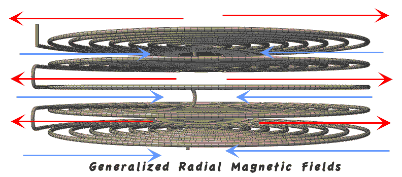
Above: Perspective View-Below: Axonometric View (No Perspective) - Purple is"magnetic core"
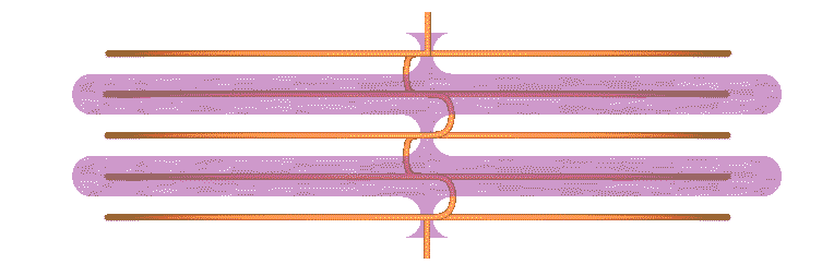
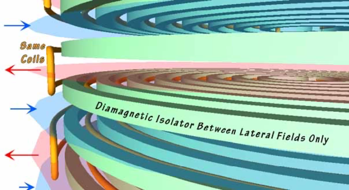
Next Below: Pancake coils emphasizing the magnetic fields wrapped around each coil conductor wire, the full length. This can be achieved in a variety of ways. With wrappings or by embedding wires in a castable, magnetically-specific composite-- Made to match a specific frequency range and....
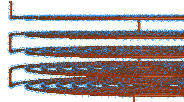
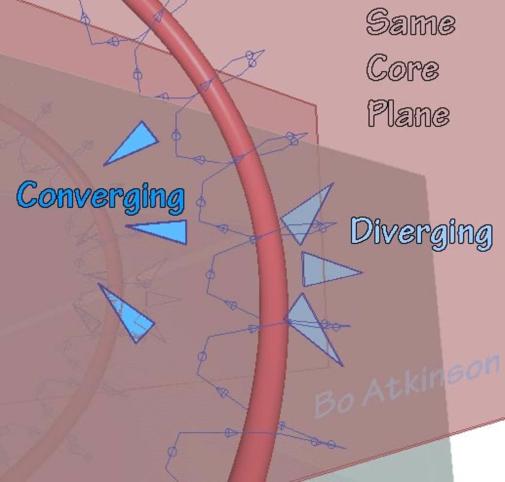
The blue helix above represents themagnetic field around a wire conductors. Can means be found to enhance this flow? Next below, suggests testing diamagnetic spacers which are modeled in light green color. Testing diamagnetic materials somewhat as 'bearings' between the opposing magnetic field segments-- In a metaphor: Is there a magnetic equivalent to friction? Where adjacent coil segments present opposing field polarities, between lateral-adjacent coil wires? Will diamagnetic materials assist in this way at all? Would such materials be frequency specific? The light red and light blue planes (semi transparent, below) indicate the magnetic fields-- To be enhanced with magnetic material. The red and blue arrows indicate magnetic polarities to be enhanced.
Below: My old flat coil modelsare held permanently in form with scotch tape. Formed upon (a junked), LP record turn table. The working voltage possibilities have been small in these examples. In that the insulation values and spaces between conductors will likely "break down" with higher power. This aspect of physics seems to favor widely spaced and less complex coil windings, especially for higher voltages and higher frequencies. Adding to that-- Will helpful materials be found to act like 'bearings? Or to consider another metaphor, could magnetic sluiceways be made? While at the same time sluice the magnetic fields to a greater operating efficiency?
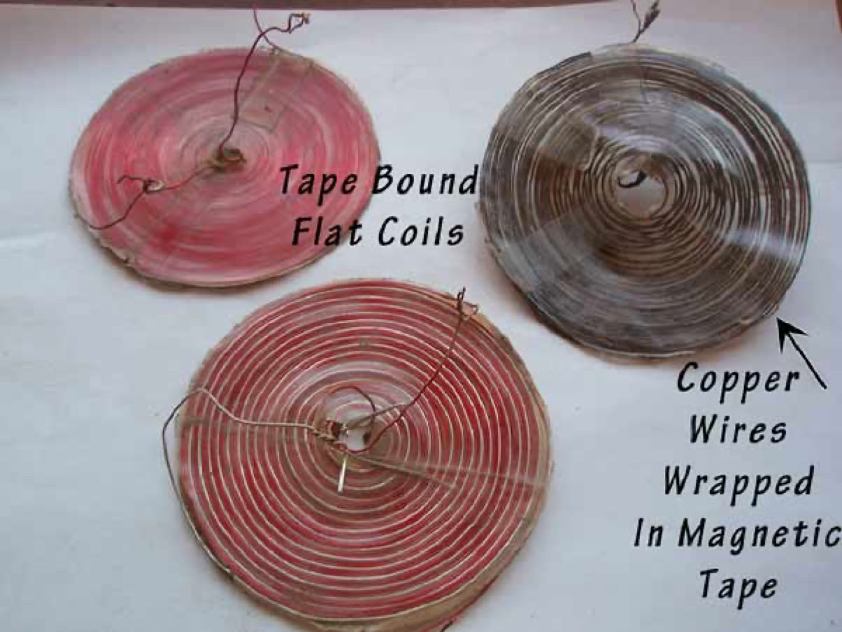
These older coils are clearly very limited. I needed to turn my focus to earning money instead. Today i consider returning to these forgotten experiments.... The purpose of the magnetic tape, was a preliminary exploration of confining magnetic fields as much as possible, close to individual wires-- To at least reduce unwanted stray fields-- To attempt reduction of mutual inductance between opposing field directions. I feel this work should be restarted. Frequency harmonics or multiplication was noted with the magnetic coatings. Writing this 2012 webpage might urge me to renew my forgotten experimental efforts.
~~~~
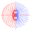
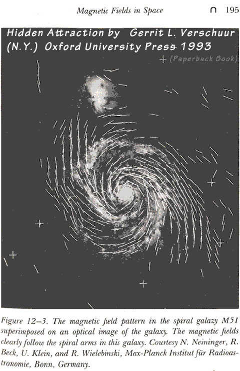
A1993 book includes this image of a magnetic field pattern of spiral galaxy 51.... Does this suggest orbital electric fields along the arms? In case helical orthogonality is helical, but not discreet, orthogonal circles, (circular orbits spaced along a path). I don't know much about this distinction or about this sort of mapping determination. However the relevance here is to consider the spiral paths. To look for imbalances according to view points.
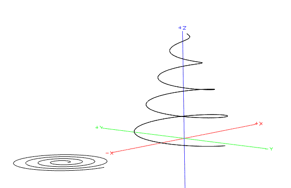
Above: Flat spiral next to same spiral elongated along Z axis-- Flat coils essentially lack a 3D path and therefore do not bear the 3D-path-imbalance of symmetry-- Except that each point along the spiral bears a unique radius-- Or in fact flat coils do have imbalance of radial- symmetry. The 3D-path-imbalanced symmetry is seen in the elongated helix. More Research: Does the elongated spiral possess an increased imbalance of symmetry? In thatboth the radius and the 3D path impart imbalances? Other polyhedral shapes provide similar potentials.
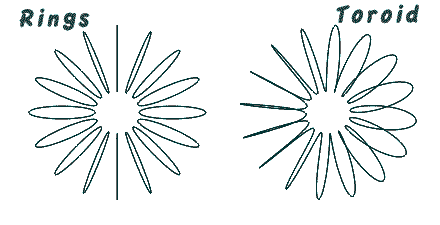
Above: Geometry render of a flat helix, scaled, with ortho-helix, also scaled. (View angle are axonometric, or without perspective ). The red extends in 3D, thereby imparting both 3D path and also a radial 'imbalance'. Next Below: A comparison of 16 rings outlining a torusand 16 turn,toroid coil. Note the balanced symmetry of the ringed torus.
So far, this page hasnoted the profiles of coils with spacings much larger than the coil substance (wire). I emphasize the scale of spacing wires apart. The spacing locates and therefore controls the fields around the wire.Where the wires approach closer together, less space is available for fields. Leading to an interesting question: Is there a coil winding (spacing) which effectively diverts the fields, away from the wires? This is the ordinary, closely packed coil winding. The fully perpendicular, no angle view presents cylindrical coils as all zigzag, no loops:
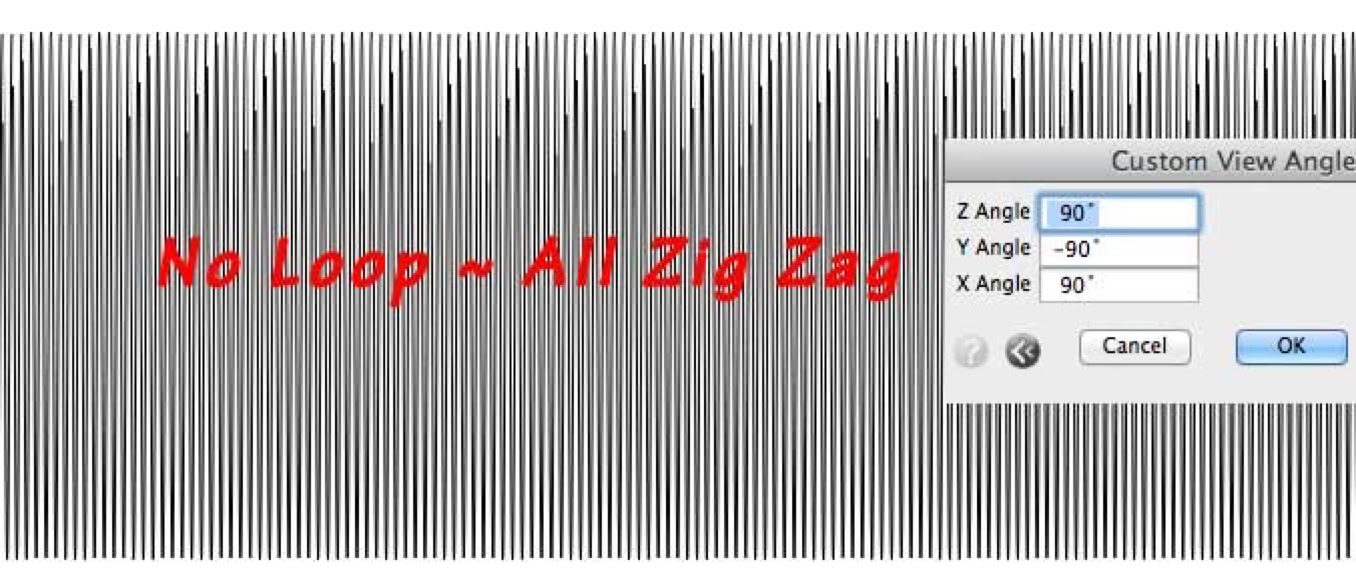
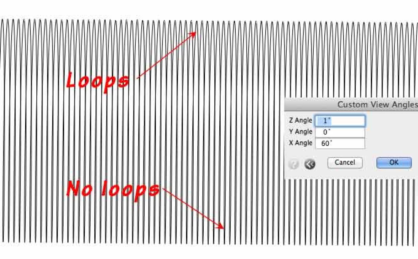
Ignoring the moire-effect of PC displays, (a purely visual display effect)... The geometry model above shows tightly spaced windings. The next image shows the same model with a slightly turned view:
Common coils have tightly packed insulated wire turns touching one another. The insulation thickness of common coils is very little and the insulation material is possibly diamagnetic. Insulation, largely composed of carbon and hydrogen are both said to have a negative "atomic susceptibility". (This according to Faraday's famous chart of magnetic responses of each of the elements. However each compound would deserve specific testing, which is beyond my means.) I've seen no discussion of this otherwise negligible consideration. I'm not aware of terms used to describe such things. Therefore i have assumed that the magnetic field between insulated magnet wires is negligible. An expensive, square, cross section, magnet wire is sold which also reduces wire spacing. Would it be sold without advantage for some application? What is the advantage in ordinary language?
There is a little more current capacity, for the same space consumption. The magnetic field lines multiply or divide the voltage measurements of combined turns or windings. This is generally called the turns ratio of associated coils. What would the effect of individually wrapping each coil winding with magnetic material? I tested a few variations of this. I'll cover this later. First to what might be related effects. Today (Nov. 2012), there are many search for "caduceus coil".With one major exception, i have considered this coil type to actually be the most common winding type-- Except for the spacing between successive turns. The spacing between concentric turns should also matter.
To the left, above, we see the inner and outer turns of the blue coil continuing with same polarityor direction. Below to left, we see the windings abruptly reversing direction-- Which would result in opposing fields.
The spacing between coils was modeled in 3D CAD to explore many variations of spacings and coil types. Coil modeling was one of my major interests in good 3D software, since 1994, (since 1995 with formZ). In real life i experimented with magnetic wire or magnetic tape windings around copper magnet wire. Itself wound on wires or filaments which were inturn formed into coils. So i got coils wound on coils, in many combinations. To see what i could see. One of my interests was the enhancement of magnetic fields between the turns of a coil.
Continuation of my printed coil"thought experiments",March 2013, modeling for a transversely wound and folded coil.
Another to study whole - individualized magnetic fields, around all conductor parts: Wind a magnetic field path around the coil conductors. Make a "core winding" around a coil winding. Above are magnetic tape and separately, nickle wire. Still other methods can be tried: Embed or sculpt magnetic putty or plastic medium around the conductors. Dunking such coils in ferro - fluid gives an immediate test case. The most evident characteristic is the loweredinductive effects, where spacing between coil turns is increased. Inductive effects are increased with tightly packed conductor-windings. Which generally explains small inductive effects of multi axial coils. But the harmonic effects urged on my quest-- As the effects of frequency harmonics raised curiosity about frequency conversion. Is this practical with some sort of coil? Will this geometry aid in higher frequency investigations? Investigation along the road less traveled? Granted thatlower inductance means reduced voltage conversions. But is there another sort of conversion? Which might tapinto a force, yet to be appreciated? Can plasma be helically manipulated? A flash of thought suggested this to me recently:
Envisaging Transverse Force Fields: Laminated, parallel coils are considered on this linked page.
2015: Summarizing transformations between spheres toruses and vortices.
What are the inductive field effects involving polyhedral shapes? Or what effects have conductors formed into polyhedral shapes? I believe the field relationships must be fascinating. Imaging these fields seems theoretical at best: Are induced fields composed of a continuous spiral orbit? Or, are these filed components like rings?
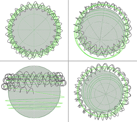
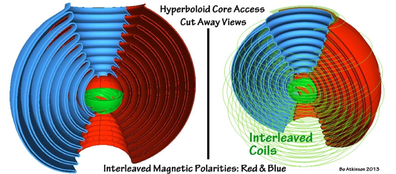
Spherical and polyhedron coils have the balance- anomaly (of 3D extents), combined with the varied radial progression, (spiraling around sphere, gradually to the pole).
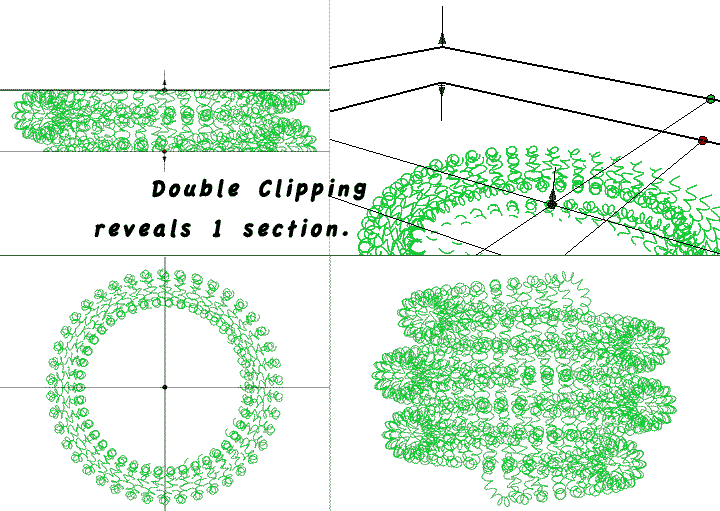
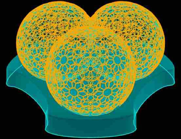
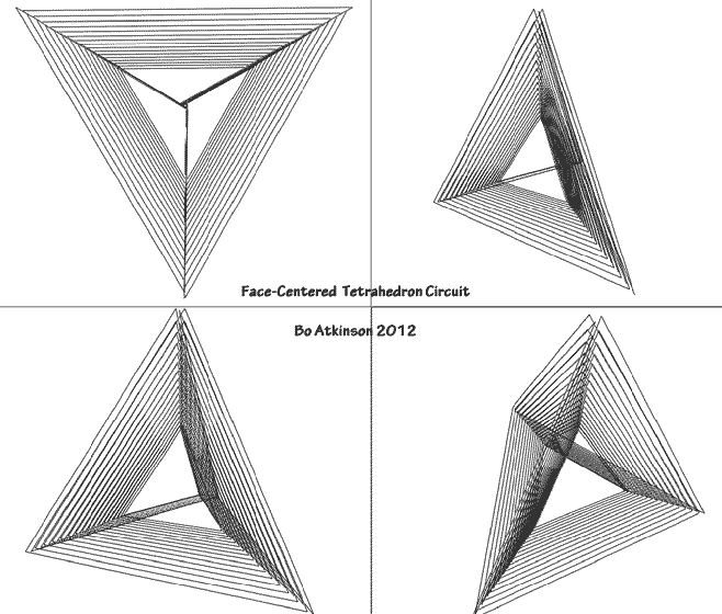
This is a complex coil wound around sphere. The software Clipping Planes manage to isolate the view of one turn. I model these paths to help formulate buildable experiments. Regardless whether the production setup is ever kick started.The polyhedrons provide endless outlines for energizing new field patterns. One of my favorite polyhedrons is the tetrahedron. I spent a lot of time modeling and imaginingexperiments for energizing tetrahedrons and derived shapes.
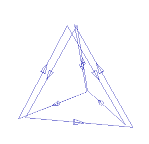
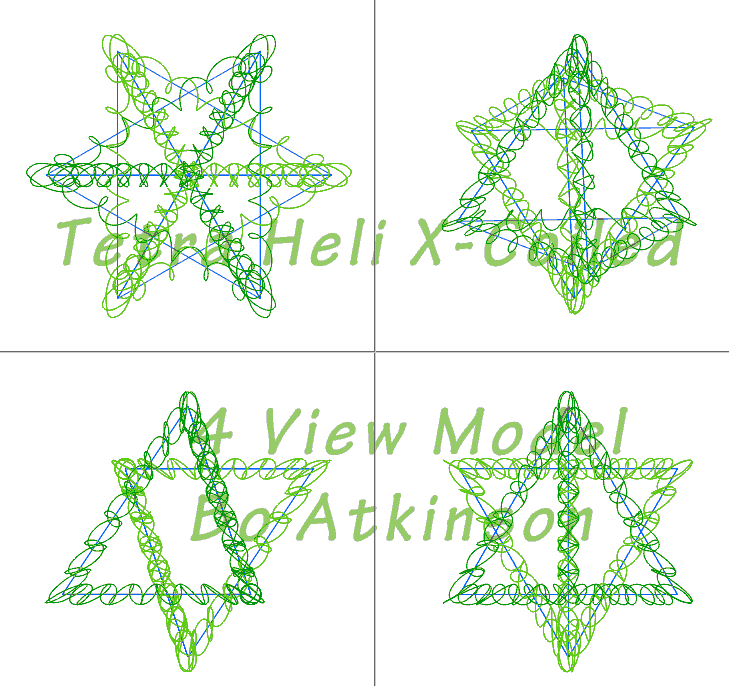
Coils structured as polyhedrons provides another area of exploration. Next below is my primordial helix combined with an inverted copy to make a star tetrahedron... Since these primal helices are themselves, in fact, facetted helices... (The startetrahedron could be made with straight bar segments.) I say that the green coils are X coils. (An older name i considered, to imply an orthogonal or circulating fields, associated with conductors).... A caduceus configuration occurs in this case, due to the closely-spaced paths. (More to be added here.)
Printed Circuit Coil.... March 2013, modeling for a transversely wound and folded coil.
Planned are some additions to this page, describing my thoughts on magnetic fields around wires and inside coil structures. I kept thinking about the Tesla's, early patent depictions and was there more than one reason for the depictions of geometrically flat coils? Beyond Tesla's famous, practical configurations, i wondered about coils or circles arrayed in flat patterns. Or force these 'flat' patterns to fit around 3D polygon shapes.
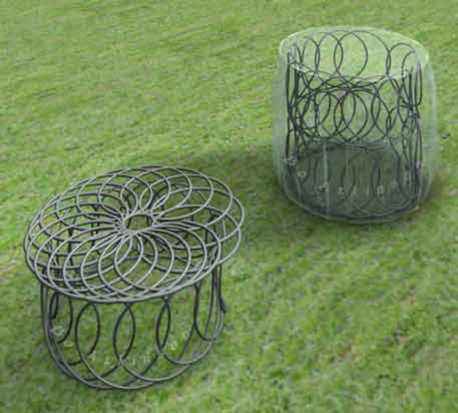
Image above is from "Ortho Oxen of Science ~ Synoptic conspectus of author's Unitary Theory". (More details are linked here). Ortho Oxen is briefly spot-lighted here, because it features spirals wound upon spirals! (My pride was here bashed;-) Helices wound about helices has always inspired my thinking.
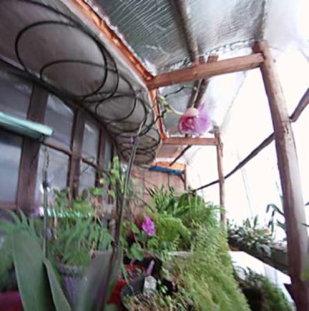
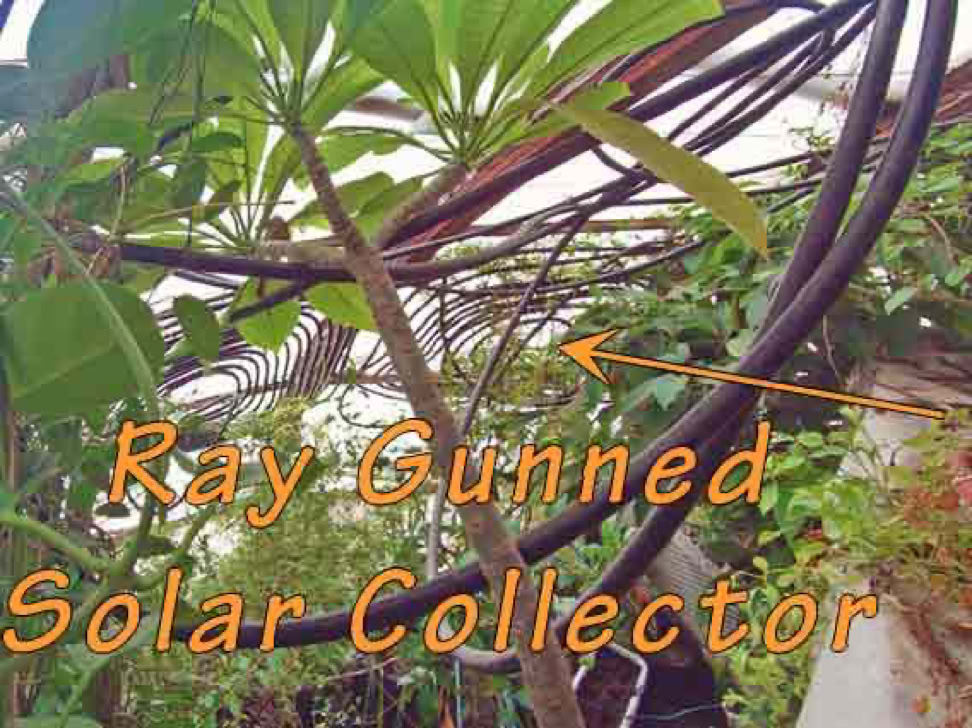
Here also are solar pickup, water heated coils.... Why would these prompt a powerful ray gun burst which caused many leaksin my solar attic.
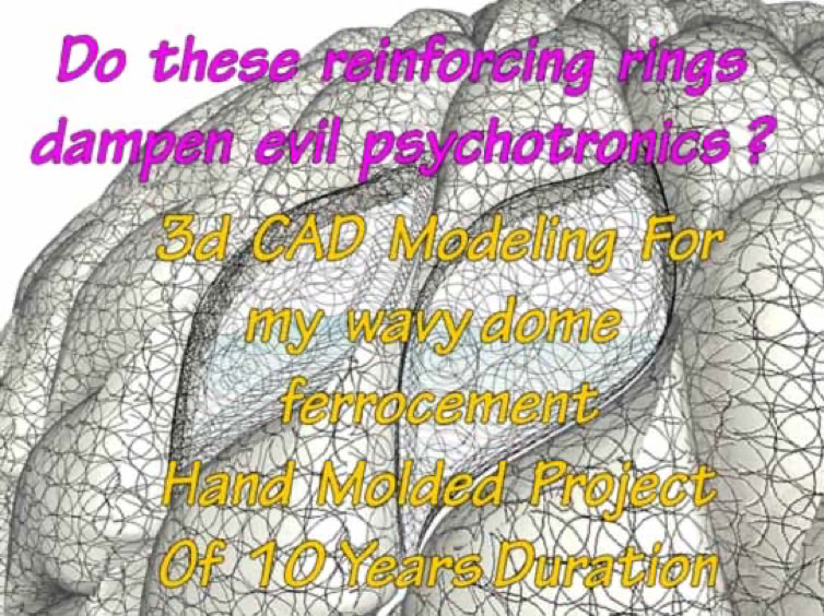
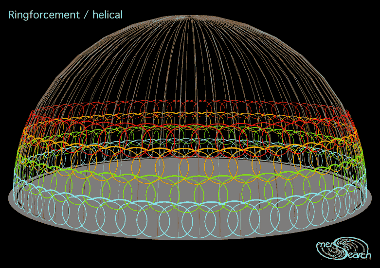
This page looks at structural concepts inspired during my ferro-concrete work.I tried to make a living with creative ferrro concrete works.

Still another section to be worked on here is this: If the above mentioned "unsymmetrical profile" has useful implications should the experimenter align a newly discoverable polarity? (Of What?) Such that coils be made of materials responsive directly to what? Which materials will particularly interact with a primordial force? Or is it entirely geometries of structures which will interact? Structural aspects of say nano-engineering structures? A classical case was addressed by Faraday. Even Faraday suggested a structural reason for magnetic effects of bisthmus.
Bisthmus and diamagnetic elements, are said to slightly repel from ordinary magnets. The chart in my book is old and does not chart frequency responses susceptibilities. Aspects of the old fashioned aether and corpuscular arguments are perhaps still interesting in that the concept of a more primal force flows through the universe-- It may interact with particular nano or micro structural arrangements or even larger harmonic structures. Or so i wonder.
A requirement may involve fitting wavelength or harmonic scales to physical proportions. Wavelengths or frequency are one parameter type. I wonder if coded reactions might also be "hidden for discovery" within reality. Metaphor should be dissected and one's vision enlarged. So winding up coils and unwinding atoms, re-welding them this way and that, may provide us primal force interactions. Thus to discover new interactions and conversions withforces to be used within reality.
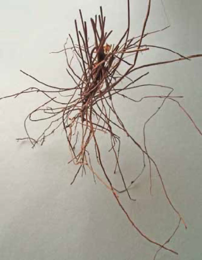
Roots traversing stem region of a fairy fern plant.This encourages me as if i work with bio-mimicry.
This page is under construction. Emailed questions or comments help me to overcome writer's block.
This link begins to describe my history. I will be adding old and new models to this page and more links-- As my life allows me to do so. In an exploration of geometry to represent electromagnetics.
My study of formal geometry is limited to use of modeling software and forum participation at http://www.formz.com, since 1995.
I would like to continue with this sort of research...The notion of working towards freely-harvested-energy has always concerned me-- That the same fate suffered by Tesla might befall anyone who might ultimately succeed with significant inventions. (With devices which could produce free electricity at low or no generation cost). Let me add an external link to an excellent author, Wade Frazier, who writes beautifully and also comprehensively, about this general subject. Today, however, with my other vocations suffering an underemployment situation... Also with the countless experimenters publishing all sorts of over-unitydevices, with public forums and commentators discussing the furtive bans on inventing energetic devices... It just seems to be less dangerous to write webpages like this one.
Some less related "rabbit hole" notes follow:
Before the 1990's, i had thought this sort of conceptualization was new and might be patent-able. Though, humble 'creatives' have to climb a slippery slope of uncertainties and detours-- So it has seemed to me based on (the scientist) Nikola Tesla's troubles and demise. Furthermore, my unrelated vocations kept me very busy elsewhere. Special test equipment and special materials were beyond my reach. In the 1980s, a library search provided some excellent reading about the "electric universe". I began to see some of my developing concepts were relatable. I xeroxed some pages for reference.The model above, actually seemed to somewhat relate to the 'poloidal' images, as illustrated in this book. When picture posting became available to the public, on the internet, i began posting some of my models.I used a shortened word, 'poloid', assuming it could function as a noun form of 'poloidal'. Within a year or two, i discovered that hundreds of whimsical images were suddenly posted on the weband that each one of these pictures came into the web search results, of the word'poloid'. Did i mean "Polaroid®": No I used quotation marks which almost always limits the search to the word in quotations. Yet the linked pages did not seem to use the word or the concept! It seemed that some entity had tagged the word 'poloid', to discourage use of this word form. Almost a decade later, i decided to change all my uses of the word 'poloid' and reword as 'poloidal', in order to become more associated with the original book usage. I wonder if small-experimenters are disdainfully marginalized,as many progressive works are suppressed, by certain furtive entities.
