A variety of efforts to spin magnetic fields are modeled and explored on this website. The primary exploration was in helical geometries. This page models a"printed coil" version. Both as a potential coil production convenience and also to study the effects of sheet like coil-windings. These particular windings are formed by etching thin separators, on copper clad, flexible sheets. The objective is to explore windings which are angled, with respect to the coil axis.
![]()
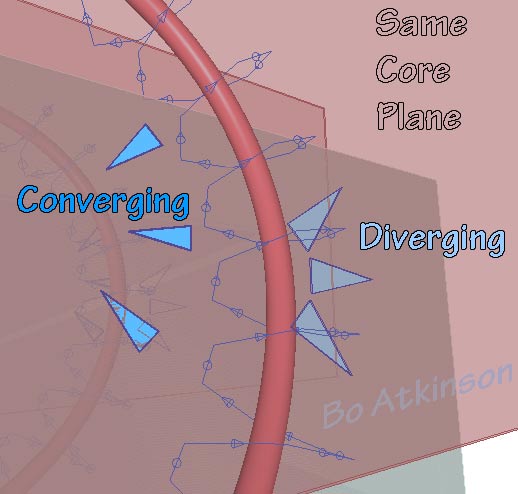
Image Above: The dark lines (separators) on the orange, (copper) represent the etching. The flexible printed circuit, is modeled and visualized to better contemplate a prototype construction process. Multiple folds are difficult to roll up into a cylinder*. Except that an especially flexible substrate for the copper might be found, which allows the multiple folds, followed by the transverse rolling up into a cylinder. My experimenter's lure has been the intriguing idea of swirling fields. The Arrows indicate the distinctive swirling of the magnetic field, which is caused by the angled electrical paths.
The purple-red cylinders are magnetic sheet material placed in between the printed circuit folds. The multi-folded, traversing-circuit-print actually swirls the the fields inversely, as detailed on this page. A transverse Vortex waveform results, with interleaved vortices. This is in marked contrast to ordinary electro magnetic fields. The individual sheets are visualized in loose configurations. This should better reveal the proposed prototyping process.
![]()
From Dictionary: "The arrangement of spiral grooves on the inside of a r ifle barrel cause the rounds to spin" ... Therefore "grooves' or separators etched into the copper may provide new emitting or field effects for coils. Next image shows printed coil, almost fully bent or rolled into a cylinder, to reveal the folds. Next is a detailed look. Dark arrows show the alignment needed to 'close' the cylindrical shape. Purple and raspberry colored arrows represent the inversely swirling magnetic flows, due to the diagonal electrical alignment.
Next is a representation of folding an etched circuit, (stating with a flat rectilinear sheet). A flat sheet is folded into peaks and into valleys, (across the zig-zag corners).The zig-zag copper paths are connected in parallel to distribute the electrical flow and to maintain the angular direction of flows. .
An important distinction of this winding configuration is that it sub divides and differentiates the magnetic core, concentrically. Two swirl directions are established. Also distinctive, is the single layers of intervening electrical and magnetic planes. To compare with traditional coil effects which lack the intervening, concentric layers. Next is the flat surface which was folded. Note that zig-zags are 45º diagonals and that the paths turn 90º respectively, upon the flat, sheet surface.
This surface model features straight and perpendicular electrical paths. Straight and angular etching should allow a hand sketched etching. (I 'm not moneyed nowadays, to the extent of buying better materials or printer-service-bureau products. In time i'll play with my old fashioned scraps of copper clad sheet, to build a crude prototype. I also welcome others to be inspired and try their own versions. (Please keep me posted.)
![]()
From the flat sheet above: The dark green triangular portions are cut off completely. (To build the rolled up version in the first images above, on this page). There are additional innovations in my mind. A couple are as follows: Double-face-clad sheets could overlap the separator etchings. This could reduce "open gaps" of the separators. Reduce magnetic leakage going through the grooved sheet, and also boost electrical cross section... As a way to investigate related effect. In case so many layers cooperate in the folding-bending process. Another consideration includes Tesla's self-capacitance patent for coils: The conductors are staggered across the folded rims, (green arrows in next image below)..
Points A & B would provide the coil terminals. The left and right ends are actually contiguous, as revealed in the next perspective view, image below).The effect of the core material between this unique coil arrangement remains to be studied. Yet the inductance and voltage between windings might conceivably be increased. While the rim connections also could be rearranged to increase capacitive effects. (Greenish arrow connections might for example
The inventive challenge to achieve this sort of inverse magnetic swirl by use of traditional copper magnet wires, also got to me. The "Flat Printed Circuit Sheet" configuration can actually be adapted with copper magnet wires. Actually a large number of wires are needed to make up the width factor. Done in parallel, this might mean countless ends to solder. (Or to weld?) Soldering might suggest less uniformity of conduction. (Or 'obstruction', considering Heaviside's suggested). More complex tools would be needed to replicate builds. Printing prototypes is easier. Therefore, the exhaustive thought experiment above, may well prove the easiest to build. To find what can be found with swirling magnetic fields.
Alternatively, the rim connectors may find paths which produce greater potential difference, between winding elements. Thus the maximum self-capacitance might be achieved. Next i add the concept of helical magnetic cores. As the cylindrical cores illustrated above could be 'twisted' geometrically. Physical definition of these cylinders might enhance the transverse flows. The colore coded paths define the electromagnetic fields:
+/- 90º 'Twists'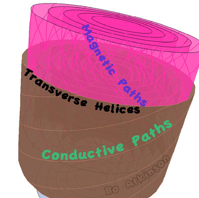
What improves magnetic cores? What would also aid the helical wave front? Would twisting core segments help? Would isolated core segments reduce eddy currents? In lower frequencies we have laminated metal cores... Alloyed wires(mu metal?) might serve this interest... These cylindrical, magnetic cores do not 'fold' as does the printed circuit- Therefore builds are not so difficult. For higher frequencies, magnetic material powders come to mind, embedded in substrates-- Magnetic recording tape has seemed to work and it seems that ferrite powders adapted to any directional polarization. At higher frequencies, could these laminated cylinders act like wave guides, integrated with the conductive paths? Is there a desirable way to enhance magnetized directions, comparable to the way in which electrical wires direct electricity? With very limited materials and equipment, i share ideas for consideration and discussion.
Bo Atkinson, Montville, Maine, USA, April 1, 2013
![]()
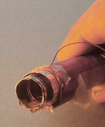
By Contrast-- Concentric, interleaved magnetic cores, with conventionally-aligned, perpendicular windings of magnet wire, align magnetic field along core axis. Seemingly without the swirling relationship. Photo below shows concentric MuMetal cores. I almost observe a normal deflection reactions with a compass needle (DC wall transformer applied to coil). I haven't tried to closely match a traditional wound coil, in terms of magnet wire length, core diameter, etc.... To compare reactions,-- On brief tests, there off handedly seem to be unexpected distictions, from usual response. However the greater objective of these experiments, will eventiually be to explore relevance to longitudinal waves, perhaps telluric waves or perhaps superposition of transverse electric waves.
Other pages describing my "thought experiments" with coils:
InductiveCouplingGeometry.html
Reflex-Vortex-Interleaved.html
Envisaging Transverse Force Fields: Laminated, parallel coils are considered on this linked page.
~~~~~~~~~~~~~~~~~~~~~
Note: My 100s of pages on this website, http://harmoniouspalette.com, are placed in the The content on this website, http://harmoniouspalette.com, is placed in the public domain only as a free exchange of ideas and as a "hard studied wish to serve life". The author assumes no responsibility for the improper use of the concepts in these web pages. All relevant laws of life and local codes should be verified and observed before any building or experimentation proceeds. discussion is welcome, please write. Bo Atkinson and are furnished "as is" and "open source". My creativity is posted as a free exchange of ideas and as my "service to others". Caution: The author assumes no responsibility for the improper use or improper misuse of the concepts in these web pages. All relevant laws of all kinds and local codes should be verified and observed before any building or experimentation proceeds.
~~~~~~~~~~~~~~~~~~~~~
Decades ago, i had started to build printed surface coils. I wanted to incorporate printed "square coils" into printed coil paths. The following photo is of a film print which i made in the 1990s. I had considered ways of using this clear film for flat-coil etching purposes. I had wanted to experiment with printed circuit arrays, like this. However, the laser printer which i had bought did not render the black lines solidly enough. This lead to concerns of eroding my etching mask. Our old-fashioned dark room needed setting up and repairs.... I did not want to loose money as this particular project was already over budget. I quit these etching efforts and moved on to other more tangible income streams. Here is a photograph of mentioned film:
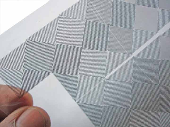
Double rows of square coil pairs were connected in parallel. The centers of each square coil wire were intended to connect through center holes, (by passing through the substrate). Connect to a coil print beneath. . I would first experiment with much simpler integrations like the following image.