Models For Provided For Steve Kornher's
CONCRETE VAULT WORKSHOP
JANUARY 15-21, 2006
SAN MIGUEL DE ALLENDE, GTO. MEXICO
I was invited to demonstrate computer-aided modeling, sand casting and coiled ring reinforcing at the workshop.
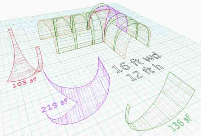
The first model was done before the workshop to explore computer adaptability for vault construction. Actual construction of this one room building was also the workshop focus for workshop students. (Eventual features will vary from this preliminary model. The modeled geometry was based on hand sketches and clay sculpture photos which were emailed to me by Steve.)
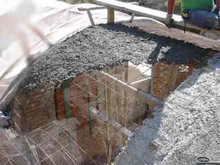
Next is a photo of some actual barrel vault building with lightweight concrete, using Steve's own methods.
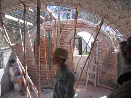
Next is the interior of same vault, showing the simplicity of form work. (Here is a link to Steve's "INTRODUCTION TO
CONCRETE VAULTS" with details on his system.
Next are two vault models addressing a concept presented by Steve: Build a lightweight concrete vault on legs to cover straw bale walls. (Since purely straw bale walls are too weak to support very much weight).
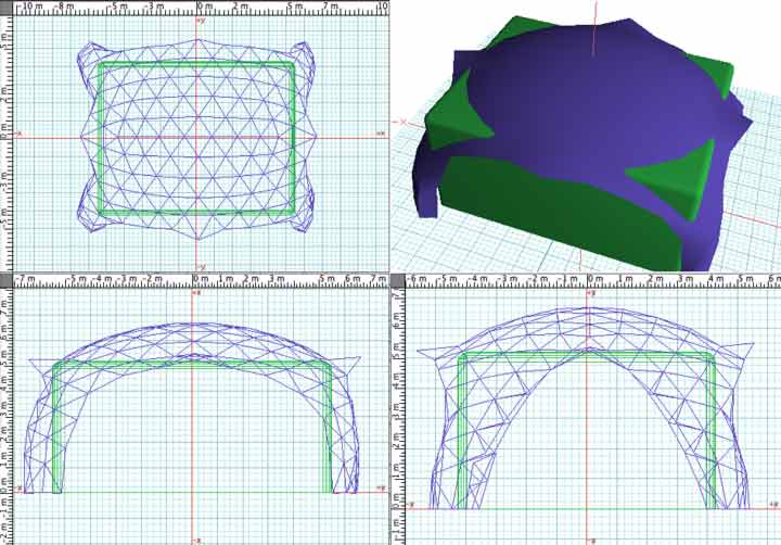
The first "strawbale vault" above was modeled with geodesic truss work. Geodesic geometry offers nearly equal length, truss like segments for structural integrity. The perspective view above was rendered as opaque surfaces to reveal the amount of coverage. At this point in modeling, choice of relative scales (of the green straw bale and blue vault) should be made.
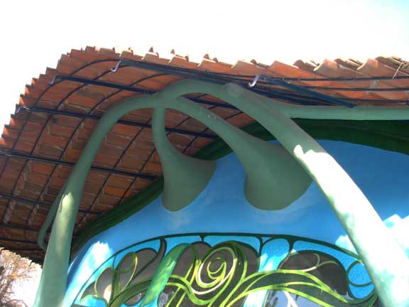
The vault could receive added roof-dormer sections or increase in foot-print size. Steve expected to use some of his cool sun screens as well, perhaps similar to next photo below? (Note, this is warm Mexico. For cold climates,modifications might be preferred to protect against ice-dam-leaks and icy-snow-loading during high winds).
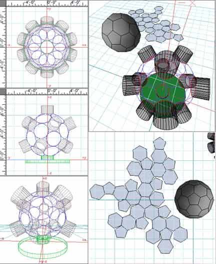
Next below is a sphere shaped model requested by a student. This model employs the polygonal facets of a soccer ball with 32 faces, (note both the larger hexagons and smaller pentagons). Use of rings was suggested to replace the hexagons and pentagons. Indeed, the unfolded soccer ball (bottom right in picture) provides an excellent template, upon which to layout the rings. (My software, formZ unfolds facetted objects easily). The rings can be tied together in this pattern and then "hinged" up with props, until the whole assembly resembles the polygonal model. Thus a "cage" of reinforcement rings can be erected, ringforce? Then, mesh could be attached, but... The student also wanted little hollow-cylinders attached. These could be shaped mesh tubes (with a ringed edge for better stability). Once the mesh and ring work is complete, the cement may be applied, ferrocement style.
Next below, is another model made for another student. It features intersecting barrel vaults. Wire and shaded renderings, interior and exterior. An average computer user could "walk" through models like this to get a good sense of modeled spaces.

Anyone can download a "demo" of formZ, and then use walk-through-navigation features on their own. I offer 3D models. Creating elaborate models requires much study, but navigating a model and setting up custom views is not too difficult to learn. Let me know if you need a model made. (boa1@pivot.net) On average, models like these would cost $100 to $200. I do need to spend lots of additional time with computer glitches and software maintenance, so this is reasonable for American pricing. Otherwise, where circumstance warrants and time permits, I offer free modeling service.
Photo below, the wavy bungalow?
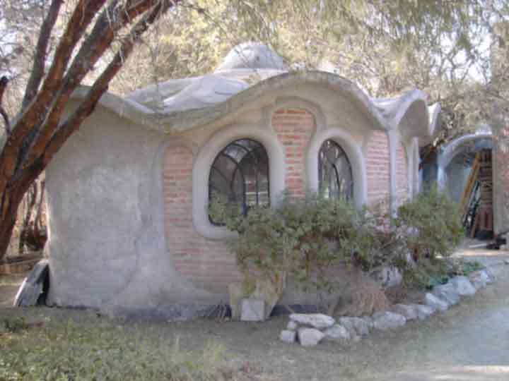
This building would take some time to detail in 3D. I did a 1 hr d model below, without correct measurements, (primarily in the dawn hours before catching a plane back to the US.)

The point of "3D Modeling" was to demo quick geometry useful for job estimates, as with Steve's catenary study below.
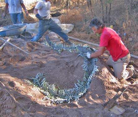
Next photo-- Steve invited me to demonstrate some ring reinforcement in a lightweight concrete vault. I was glad to install rings and get a feel for the "espumia"(?) It is great stuff for building in the "flying concrete style".It is a light weight aggregate which comes from local Mexican pits. The rings are actually contiguous flat coils, spread out to bind more load-bearing points throughout the concrete volume. The lightweight espumia aggregate is soft and I theorize that the fine, (cheaper) wire, contacts more of the available cement paste constituent, (the denser component in this mix). Therefore a higher flexural bearing of stress may be achieved for less money. Harder and stronger steel in the 6X6 mesh might flex less readily and thereby separate from the soft aggregate, (during highly stressful events). Well spaced coils of cheap wire may better match this soft, lightweight aggregate. I love using a cheaper material that works just as well, which proves easy enough to apply and which doesn't wound us, (like factory-made mesh wounds many a laborer). Below-- Bucket pouring and continuous flat coils of wire, "rings", being applied by me.
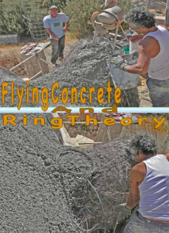
The broader and bolder hypothesis is that for equal chemistries and weights of steel, finer rings will out perform traditionally-thicker geometries of reinforcement under the same physical tests. Think of it: Nature doesn't use long reinforcement bars, but instead, molecular chain construction. This ring theory is somewhat modeled on molecular chains, but with cement as a compressive binder. Coincidentally, I've noticed on NOVA/ http://www.pbs.org/wgbh/nova/elegant/program.html --That String Theory has also taken up a form of rings to depict it's theory. What is next?
Here is more on Bo's ring theory- ringforcement.html (is there a ring force?) The content on this website, http://harmoniouspalette.com, is placed in the public domain only as a free exchange of ideas and as a "hard studied wish to serve life". The author assumes no responsibility for the improper use of the concepts in these web pages, as all relevant laws of life and local codes should be verified and observed before any building or experimentation proceeds. discussion is welcome, please write. Bo AtkinsonWire ring theory also addresses stronger cement mixes, stronger wire and strong monofilament plastics, (like PVA). I would be glad to help prepare samples to test ring reinforcement in competition with other configurations of reinforcement. Until such a lab test opportunity is made available, we are stuck with simpler testing. Steve has come up with his "meteor" test andthat would be fun to try. We ran out of time. I might generally prefer testing which employs accurate strain gauges which can be simply set up to compare failure levels of competing panels as well as structural joints with various shapes.
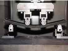
Picture above shows lab testing of a thin cement based panel. I would love to submit ring reinforced panels to test in this way. Anyone?
More on workshop: Bo's sandcast models included a stand for lantern, (photo below), and some birdbath pieces. Leaves in this photo are artichoke, from Steve's garden. Bo offers similar apprenticeship training in Maine, USA, during warm seasons.
In the next picture below, I attempt to clarify my interest in braided reinforcement. I modeled some braided reinforcement using available wires. I prefer to disperse the steel (or mono filament also) as much as possible within the cement or concrete form. I used Steve's half inch drill to twist up some thick, soft steel wires. I prefer to use stiffer, springier wire which has greater tensile strength. Springier wire, if twisted along a suitable shaft will spring back slightly. Enough to easily remove the wires from the shaft. Instead of tight twists, one can have "dispersed braiding" which therefore binds more cement within a "caged" compressive zone. Cement withstands compressive forces very well. Steel or suitable plastics withstand tensile forces well.
I'd like to elaborate with better pictures. Other site links are also invited. Here is an older picture which shows more applications.
Picture Below: The Chinese Finger Cuff (perhaps 1000s of years old) was perhaps the first employment of "braided reinforcement".
~~~~~~~~~~~~~~~~~
Some workshop photos were taken by participating students, (missing names will be posted if made available).
FranCisco Vargas
Arnold Mainland
David Evans
The content on this website, http://harmoniouspalette.com, is placed in the public domain only as a free exchange of ideas and as a "hard studied wish to serve life". The author assumes no responsibility for the improper use of the concepts in these web pages, as all relevant laws of life and local codes should be verified and observed before any building or experimentation proceeds. discussion is welcome, please write. Bo Atkinson
Below: Earlier sod approach, load-buttressing, castle corners