The generated trihedral-helices on this page differ slightly. Observing many differing ratio-results tends to suggest that the larger the ratio, the closer this facetted helix type outlines closer to a pure tetrahedron. (However the equilateral tetrahedron has always measured slightly shorter in profile and is slightly less steep. The angle differing by a little over 1.5º).
The following content was first posted in 2009 describing... a well-formed formula-based helix which actually generates a trihedral structure. My professional modeling software consistently generates this geometry based on automated math and therefore this has seemed significant.
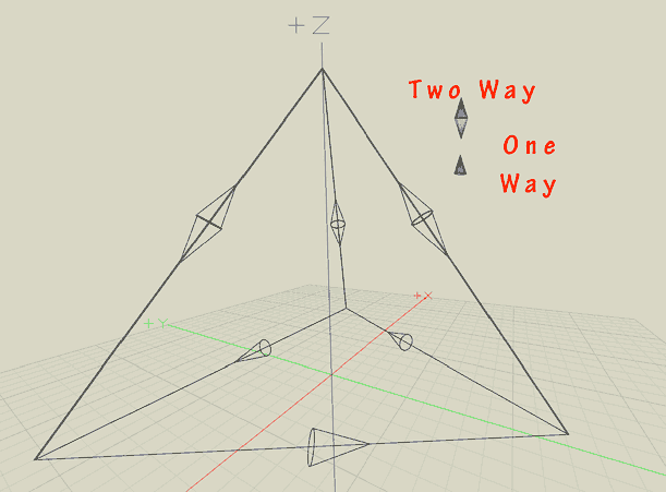
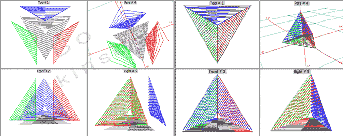
These trihedral paths are apparently a form of helix. A helix and a trihedron, both, apparently. A nine segment (faceted) helix formed along an equilateral triangular path can actually actually form a trihedron. Wire frame model below shows the helix-segment directions. This helix radius example is close to10 times larger than the triangular-path, (along which, said helix does form), and the edges grow closer as described below.
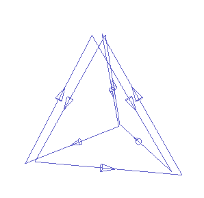
These tetrahedral paths are apparently a form of the helix. A helix and a tetrahedron, both, apparently! A nine segment (faceted) helix formed along an equilateral triangular path can actually actually form a tetrahedron. Wire frame model below shows the helix-segment directions. This helix radius example is close to10 times larger than the triangular-path, (along which, said helix does form).
The "show-direction" render immediately looked like an interesting coil for new, tetrahedral EMF effects! As the ratio of radii is increased, the alignments of the helix segments more closely align with a superimposed, precise tetrahedron. There are many interesting aspects of this geometry.
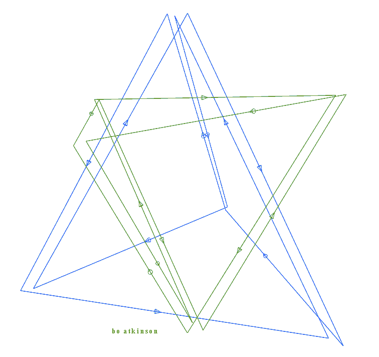
The first two examples were generated using a 10:1 ratio. (The ratio is helix-radius to path-radius). A green-equilateral-tetrahedron is compared with a blue tetrahedral helix in the picture below.
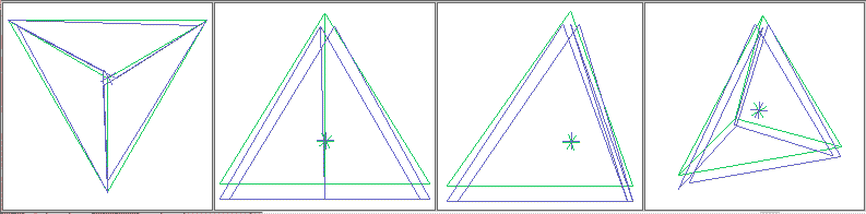
The generated tetrahedral-helices on this page differ slightly. Observing many differing ratio results tends to suggest that the larger the ratio, the closer this facetted helix type becomes closer to a pure tetrahedron. (However the equilateral tetrahedron has always measured slightly shorter in profile and is slightly less steep. The angle differing by a little over 1.5º).
The helix radius in this example immediately above, is many times larger than the triangular source path radius. (Ratio differences at work). These are screen capture images from 2009, (using formZ):
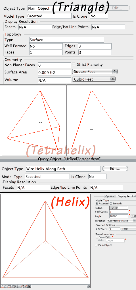
The red tetrahedral object (immediately above) is the "Wire Helix Along Path". The small black object (visible at higher image resolution, would be the flat triangular path. Downsizing image for bandwidth conservation lost the black colored pixels).
So next is a model with a larger, red colored source-path triangle. (Barely visible even the low resolution image).The resulting, facetted, 9 Step helix, (3 'turns' per cycle), was then Swept or made into a solid to emphasize the approximation-feature, of true equilateral tetrahedron rendition.
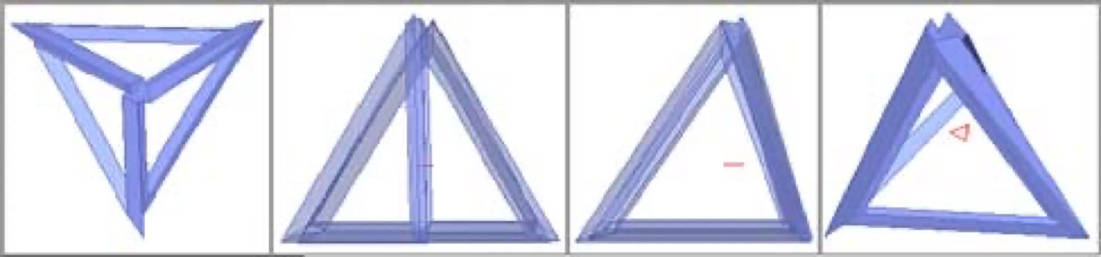
The fact that an equilateral tetrahedron does not follow this helical procedure, with the shorter height, actually may prove usefully suggestive. It may render advantages in case the helix path could become a solid wire. My curiosity is drawn to bifilar tetrahedral legs. The "slightly mismatched" vertices can represent the layout of bifilar arrangements, as these would 'angle' at the vertices. Question: Would the features of this primal-helical tetrahedron provide other significant field relationships?
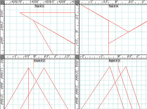
The images directly above reveal a consistent limitation for the trihedral helix. Regardless of seemingly large ratios, there always appears to remain gaps at the vertices, visible in top-most corner to the right, and as a centrally projected equilateral triangle. As in "Top#4" view above. Me must ask for a seed-equilateral-triangle whose radius is the very smallest possible to compute, with the largest ratio it can compute or generate. What sort of resulting trihedron will then be mathematically generated? AI may easily be instructed to find its most extreme available radioed inputs to compute. Does such a formulation more closely matched equilateral trihedrons and tetrahedrons? Would a further developed AI get closer still, and would it ever compute the absolutely smallest size in nature, perhaps a hypothetical, primordial atomic scale?
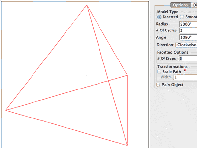
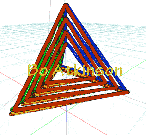
By contrast, the facetted helix in the image below has a relatively low ratio. As a result, the helix facets or segments do space further apart. Observing the results of differing ratios helps visualize the geometry of this primordial tetrahedron. The stellated tetrahedron can visually suggest a winding to electrify, because the eye can quickly trace the 9 segment trihedral coil.
My own interests span various fields of endeavor, only partly technical in nature. The blue segmented helix framework above suggests producing a specialized magnet field to text with better equipment than my burned out frequency generators.
By changing leg connections and hence the field directions. The blue framework can add two more equilateral triangular windings to contain all closed face windings.. Visualizing the tetrahedral star circuitry below was added to this page on Nov 2012, and additional drawings are needed some time ahead.
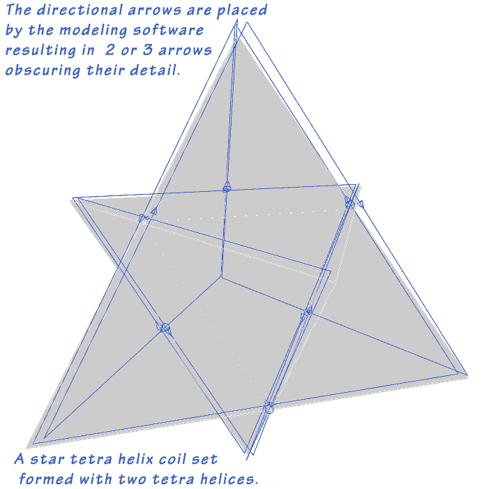
Next is a view at a slightly different view angle. Notice also that the spacing of the wire frame models vary. Each model is utilizing a different ratio between the source path, equilateral triangle and primal helices. (These may yet be adapted to more intricate frameworks like my Fractal StarTetrahedron. Visualizations of the expected trefoil, Split pole, field effect, deserve some time spent in future.
The fact that an equilateral tetrahedron does not follow this helical procedure, with the shorter height, actually may prove usefully suggestive.. It may render advantages in case the helix path could become a solid wire. My own curiosity is drawn to bifilar tetrahedral legs. The "slightly mismatched" vertices can represent the layout of bifilar arrangements, as these would 'angle' at the vertices. Question: Would the features of this primal-helical tetrahedron provide other significant field relationships? Would a finite element analysis app have been taught to recognize such significances of a tetra-helical arrangement, which nature had provided through helical laws of projection? The following trial should be requested next.
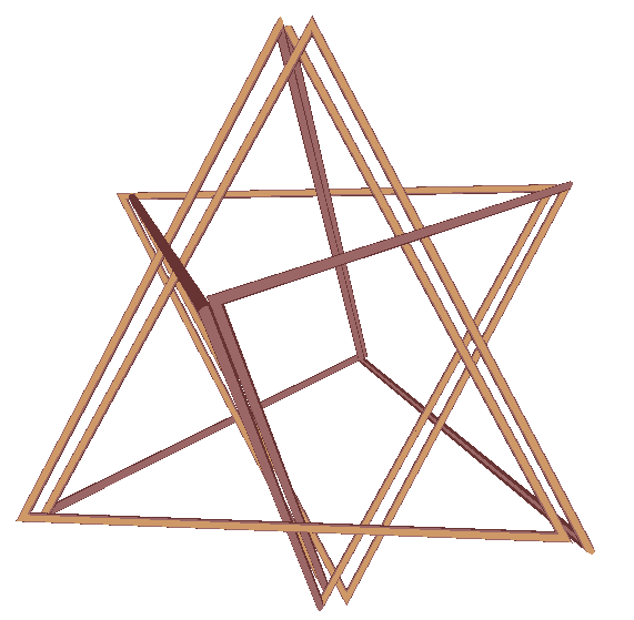
Yet another model below visualizes a quick render emulating copper bars with sharp corners. To emphasize the physical challenge of forming and 'perfecting' a copper, tetrahedron circuit: The close bars/wires would be insulated but touching. If not to use square-cross sectional conductors. (Yet another experimental issue to study.).
Next model below explores a flat faced tetrahelidron, for research with wave guide effects. The plate separation is exaggerated to represent insulation which allows this configuration to form a series electrical path around all plates. (through centralized interconnection).
Next below is another pending example for proposed PCB research. On right below is a tetrahedral arrangement of 'coils' and to the left is the 'disassembled' or spaced out assembly. To emphasize the geometry of the arrangement of 4. conical coils.
My expectation is that the above configurations would provide more centered foci of magnetic fields. Apex openings would offer ingress for probes if two were joined at base. One of the joined trihedrons would be wound opposite to the other for polerization, and otherwise to treat as in the radicoil experimental findings, (as complimentary experiments)
I would closely compare and adjust the resultant field concentrations towards the tetrahedral center. At the most central point, the three uppermost fields could 'funnel into the bottom most coil field. This construct could be studied alone or as one intact component within larger configurations shown below.
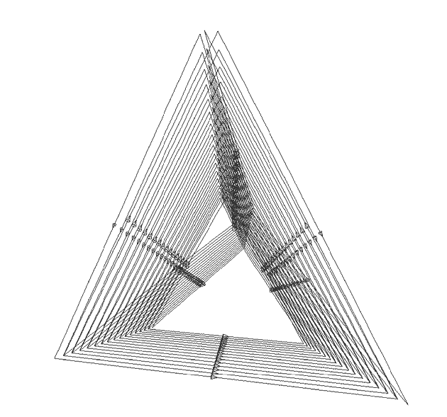
Further connection examples examples may be contemplated. Electrical, printed circuit board materials are on this Tetra- Isotropic Coiling page. There also remains the fact, that 3 legs of the primal tetrahedron (heli-tet?), have wires with opposite alignments (or polarities). While the remaining 3 legs are single wires. I would elaborate on my work with these assemblies as more observations are collected from future experiments. I would have enjoyed experimenting with better equipment, help or training during youth. My experimental coils are a little crudely wound, and deserve better resolutions, as with PCBs. A splurge of money is needed to hire a PCB shop to print the wires, followed by some good bending tools and bench vises.
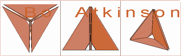
A mathematical helix formula generates three surprisingly aligned surfaces resembling a tetrahedron. Two sandwiched, printed parallel faces are finely separated in reverse windings to result in unified field production. A scaled down siid fits the inner trihedral winding inside of the outer face coil.
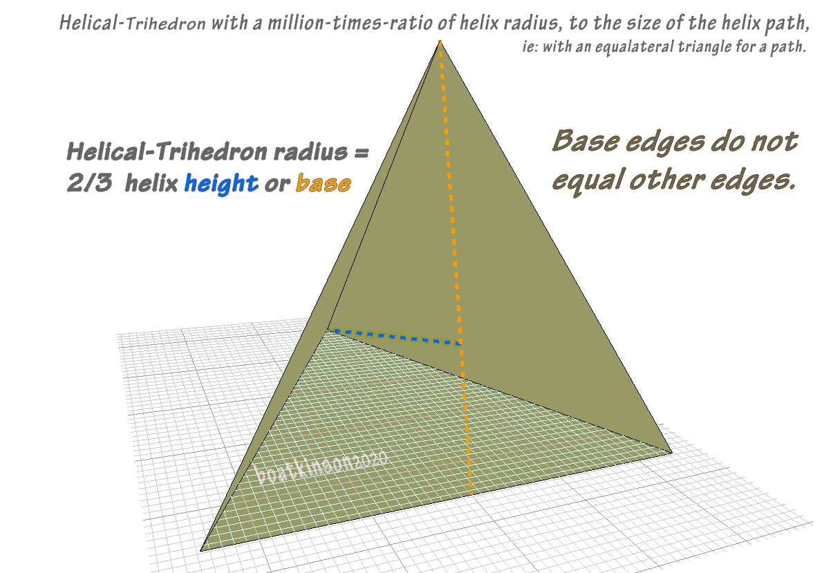
A more acceptable name might be Helical Trihedron, to replace the earlier suggested name of Primordial Tetrahedron, where the earlier question of antecedence is still open to discussion.
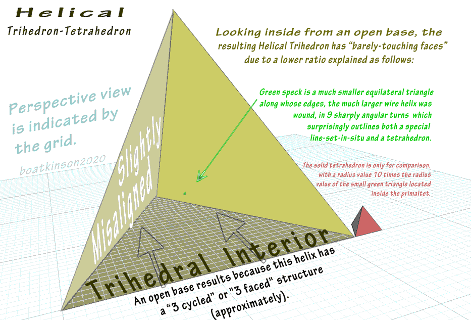
In February 2007 I modeled and observed helical structures wound around basic geometries including the equilateral triangle and by adjusting the input parameters discovered the striking resemblance to the tetrahedron, or trihedron as described above. The convergence or transmutation of two dimensional (triangles) and three dimensional structure (polyhedra) was questioned, as a hypothetical explanation, (hence the previous suggested name Primordial). The three apexes increasingly converge with the increased ratio of helix diameter to the helix path, (and structured with straight segments instead of curves). This peaked curiosity about the classification of “2d vs3d”.
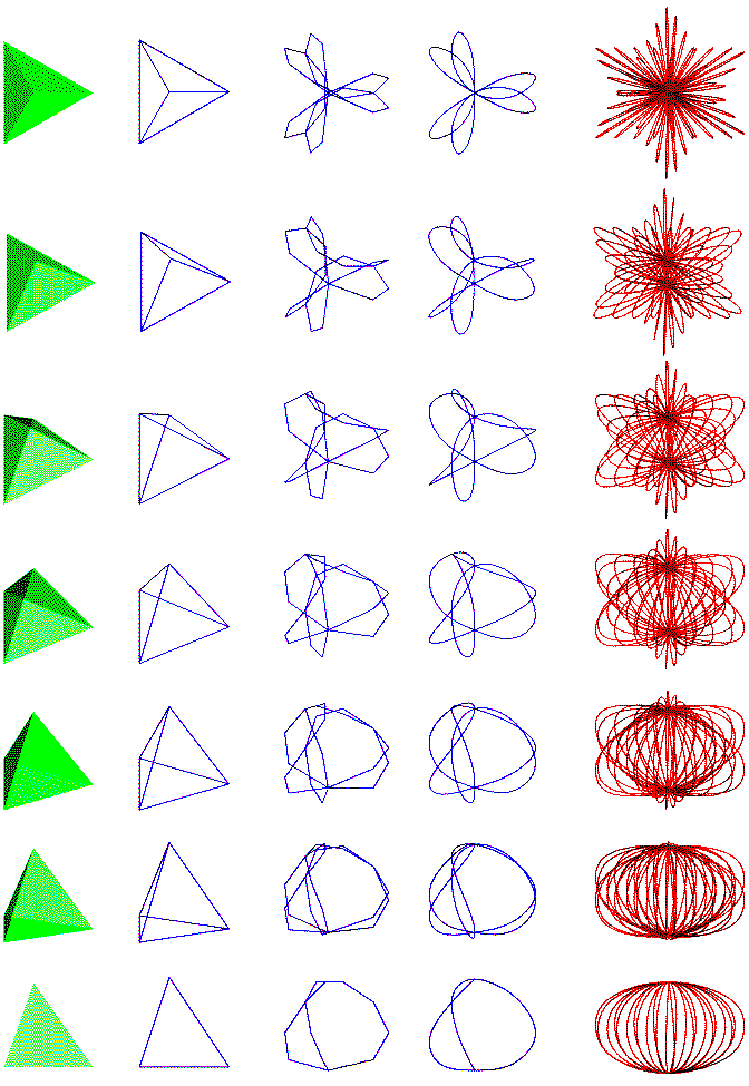
The relevance of this geometric discovery of a particular relationship between the helix, the solid tetrahedron and a simple, flat triangle was stimulating. The next image views the same helix object with variations of steps-per-cycle, (from differing view angles) and includes a solid tetrahedron for comparison, (in green). The image includes variations of helical frequency and curve-smoothness, wound around a triangle. ~ TetraHelidron?
Discovery of this particular trihedron was as follows:
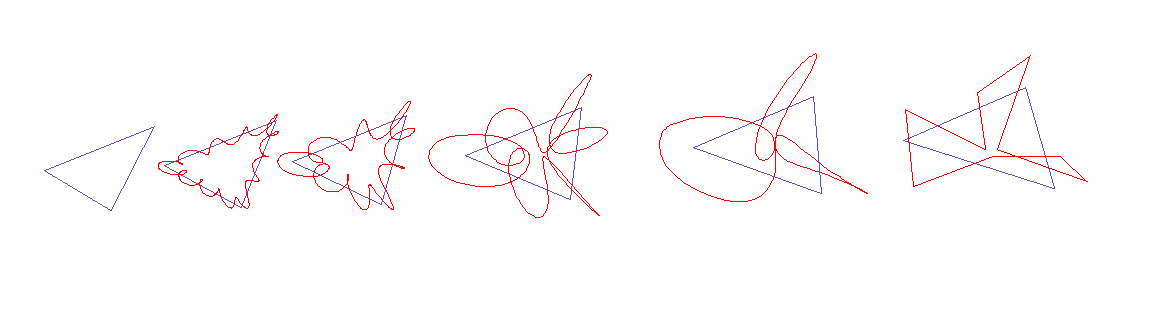
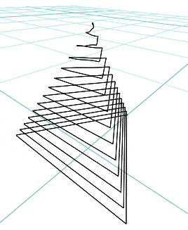
Next images below were earlier efforts to convey what it means to form or wrap a spiral around a triangular path. A smaller scale helix is used and the helix itself is shown with a variable number of turns and variable segmentation just for a start.