 ...Bo's pictorial index spanning over 2 decades.
This 2014 visualization of orbiting magnetic fields was initially inspired by my reading about the Searl Effect Generator. However, electro magnets are not featured in the SEG. (Many SEG references are found on the web and i am not familiar with most of the sites. Here is one site: searlmagnetic.com). The SEG components appear to be very precisely machined and therefore difficult to replicate, (according to my understanding). Therefore my imagination compelled me to visualize experiments with flat coils in a planetary arrangement.
My Open Source Thought Experiment Purpose: To see what effects orbiting, electro-magnetic fields might have. In this experiment, magnetic fields will be energized electro magnetic fields formed by loops (or turns) of pulse-energized, physical-wire-loops. The visualized, magnetic fields are polar, indicated by traditional red-blue lines of force. The simplified concept above suggests that pulse timing could energize loops and speedily orbit the magnetic fields. Fewer loops are spaced apart to simplify the principle schematically. Greater quantities of individual loops are intended for flat coils (as visualized further below). I invite comments, (but cannot enable visitor comments on my low cost website).
I will attempt to show multiple ways to apply the concept of orbiting, parallel, magnetic fields. Matching pulse and coil characteristics are explored. Hand made flat coil development is supposed in these concepts. Matching a flat coil with wave types might produce favorable effects. Easily built coils, using hand wound methods, are expected to fit the microwave band of frequencies. The size of the human hand comfortably handles physical loop or turn lengths, suitable for wave pulses in the microwave range. Other bands of frequency might be considered with other sizes of coils. Ease of hand building simplifies the visualization process.
The first of several visualized magnetic fields are spaced apart with an equal, null duration, (or non- energized turns between pulses).
The purpose of a (right-triangle) “saw tooth pulse shape” would be to maintain a steady voltage rise throughout one physical-wire loop or turn. The steady voltage rise ends with an abrupt de-energizing. (A persisting null could follow which would have an electrical length equal to a length required to reach the next desired energizing zone. Thus, exactly 10 energized turns might be developed as illustrated above. Other frequency modulations and/or spacing schemes are also supposed, which require tailoring the pulse characteristics accordingly.
Objective 1: Match the rise duration (of the voltage-current), to the length of the physical-loop (or full turn) and material types.
Objective 2: Space out and shape the pulses to form orbiting, energized zones.
Objective 3: Explore variable geometries of flat coils and wave types (pulsed vs plain AC).
Objective 4: Ascertain comparisons between orbiting permanent-magnets vs orbiting electromagnets.
Objective 5: Categorize individual visualizations and insights.
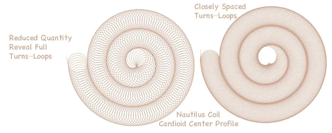
Distinctively energized zones might be situated closely or situated further apart, according to the pulsing characteristics. The quantity of energized zones could be varied. Increased spacing between energized zones (or magnetic fields) is visualized . The magnetic fields are thus spaced further apart. The pulses can also be spaced further apart, (with time delay). Pulse widths might be varied to span several or more loops (or turns), providing that a central "unenrgized core'' is maintained. (Such that a somewhat round or elliptical, energized shape is maintained".)
Increased spacing between energized magnetic fields is considered. The magnetic fields are thus spaced further apart. The pulses would also to be spaced further apart, (with increased time delay between energizing). The pulse delay would be engineered to match the desired spacing.
I have been thought-experimenting with flat coil concepts for years. New insights continue to stimulate my imagination. I manage to afford some experiments with winding methods for coils. However, electronic testing of these coils demand purchases, (likely beyond my budget). Computerized visualization seems to satisfy my curiosity in many respects.
From my limited understanding of electro magnets, it is the change in electrification of a coil which induces or transfers power. Rotating or moving magnetic fields power motors and generators. These useful principles apply both to “permanent magnets” and also to electromagnets. These conventional uses of magnetism, generally align all of the magnetic fields in one direction. The key alignments are generally of one coincident axis alignment. Whereas the key alignments of orbiting magnetic fields never share one coincident axis! Alignments are multiple, parallel axes.
Common electric motors orient magnetic fields 90 degrees to the common center, (motor shaft). Axes align through centers. Planetary flat coils share axes in parallel:
I've not seen this type of magnetic arrangement outside of the Searl Effect Generator. Therefore my continued curiosity has invested time to wonder, just what are the natural principles involved? Next is offered concepts of ten toroidal fields viewed statically, joined as one field and also joined in greater fractal aggregations. (Galactic?)
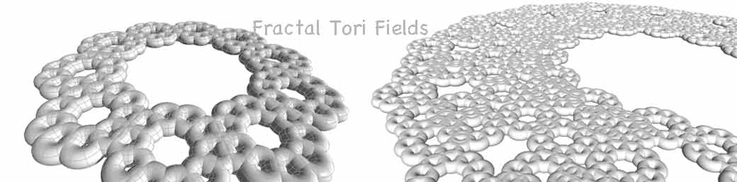
I tend to ponder principles at many scales from micro to cosmic. Can the combined fields orbiting together be considered as one fractal field?
What further attributes and principles may be discovered about fractal tori? Is there any sort of patterned relationship here, relating to planetary mechanics in a solar system or perhaps even with atomic constituents? Will consideration of galactic shapes and patterns provide insights here? Other natural, functional, vortical patterns might also deserve consideration.
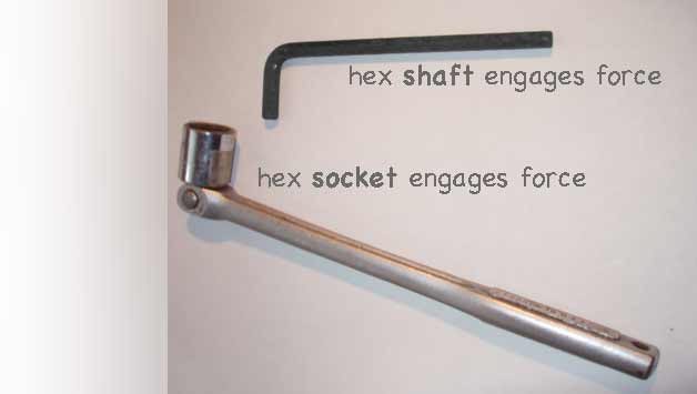
Shaft drivers vs socket drivers may be a suggestive metaphor to compare an individual field attribute vs orbiting field attributes. The orbital configuration can impart more force transfer efficiency, as compared with a single shaft transferring force. In mechanical work the stronger, marketed fasteners are driven with sockets. While the lighter duty screws and bolts are driven with centralized shaft like drivers. The driver requires more durability for repeated uses over the years. Shaft driven fastener are largely used just once. Reused shaft driven fasteners deteriorate very easily, but used just once, may last indefinitely. Will fastener functionality convey insights about magnetics? I seek insights concerning the geometric axis planes of magnetics. How may the electromagnetic effects be explored?
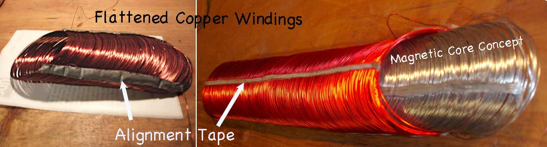
Can wire like materials enhance the magnetic core of a flat coil? Would a magnetic core sandwiched in between flat coil windings enhance or deter orbital mechanics? Common electromagnets usually consist of many turns, stacked together, along a shared magnetic core. This strengthens magnetic induction involving lower frequency electrical currents. Will flat coils find practical uses at lower frequencies? Are core materials a necessary consideration? Perhaps open air or specialized cores are needed for orbital field propagation. It might seem possible to shape clusters of pulses or modulated waveforms to energize orbital fields in this type of coil arrangement:
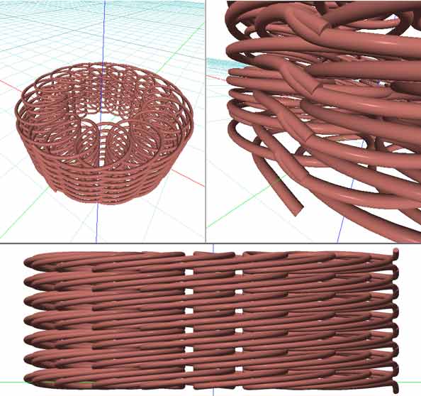
Also, another pattern of interest is the flat, nautilus coil arrangement. I found it interesting that while modeling this with precise software tools, a cardioid shaped center resulted.
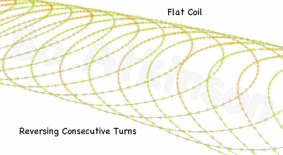
Contemplating the use of plain AC, (alternating currents), inspired the concept of inverting consecutive turns, in a flat coil. First consider just one set of inverting turns:
Will such an electromagnetic winding, repeated consecutively in a flat coil, maintain magnetic polarity in one direction? Providing that each coil turn is equal in length (circumference), to the electrical length of one-half cycle. (An equilateral sawtooth wave might be compared for effect.) Will distributed capacitance defeat all efforts to match a steady frequency with a practical size of a planetary coil? Will tuning adjustment allow plain AC to match two turns exactly?
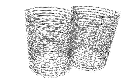
Extending this visualization revealed a unipolar electromagnet arrangement, which aligns both the inside and the outside magnetic coil in one direction: December 2016 ~~~ My Latest Electromagnetic Research On A Radical Radial Pole Coil.
The newer special windings could compare with the plainer flat windings, (as pictured below), with the objective of advantageously modifying the resultant magnetic fields, due to the tightly parallel windings which might adequately maintain a unipolar effect.
Will there be found flat coils which engage natural forces directly? Flat coils which pickup natural occurrences of naturally-existing, tube shaped forces, as opposed to conventional reception of radio waves? Would greater numbers of coil or inverting 'fractal' arrangements, with appropriate wave forms, solve the needs for working with lower frequencies?
Will there be found a method to harness self induced currents upon a planetary coil arrangement? (Image above can suggest alternating both inner and outer connected turns of flat coils. Image might encourage further possibilities for fractal coils).
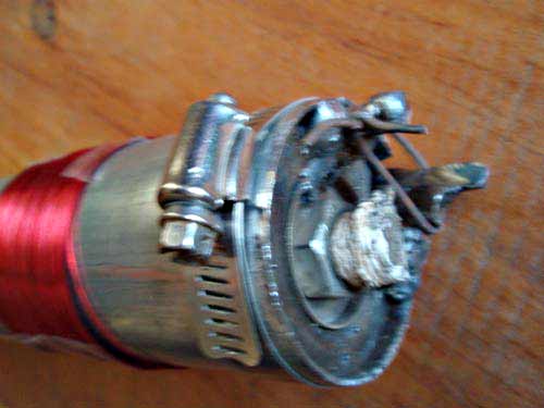
I have tried several methods to wind copper wire coils specifically for use in flat coils. The copper windings should ideally release easily, but instead the copper wire tends to hold it's position and not release easily. By comparison, springy wire like highly-tensile steel welding wire tends to slightly unwind itself, just enough to slip off the coil form or bobbin. Therefore i have tried to fabricate bobbins which can be squeezed into a smaller circumference. The photo above shows that a pipe clamp is used, on a thin piece of EMT conduit pipe, previously kerfed (cut) lengthwise. Conduit tubing, with very thin walled steel allows for a small reduction in tube circumference. Steel allows welding of fixtures, like the shown studs to hold circumference smaller- While the pipe clamp is remove- To allow slipping off the wound copper coil. For very long coils, better release mechanisms are needed. I will detail more of this continuing effort on a related page: Quadrantal Toroid Visualizations
A Disclaimer, which might suggest this thought experiment is futile: John Searl has demonstrated that permanent magnets will naturally orbit and produce very important, practical results. (Web search "Searl Effect Generator" for detailed information). I think that Prof Searl might have written that the SEG effects would not be reproducible where electromagnets might substitute for his permanent magnets. (I found writing to this effect, in one of his numerous PDF downloadss. I have not had the pleasure to read his more comprehensive text books.) My curiosity nevertheless inspired me to see as much as possible, what mimicry or effect were possibles.
I cannot afford visitor posted comments on this low cost website. Comments are welcome: ![]()
All visualization and construction art work is by Bo Atkinson in Maine, USA.
Here are some of my coil visualization pages with additional links within each web page:
InductiveCouplingGeometry.html
Reflex-Vortex-Interleaved.html
HelicalWaveTransverseCoil.html
My index page is mostly pictorial, linking to decades of my varied occupations.