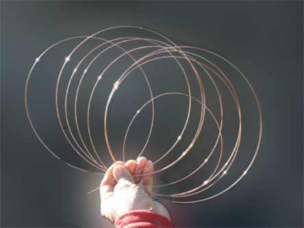
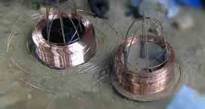
This page reports on some gradual progress with coiled mesh prototyping. First a finger formed mesh is shown in first photo below. Using stiff welding wire, the loops fan out easily and can be planted in wet cement for reinforcement. Wet cement will hold these tensioned loops in place. Multiple sets can be overlapped to form a continuous mesh effect.
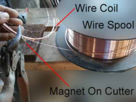
Next, below is a simple cutting station. The cutting tool itself is held by a strong magnet and the cut end from spool is caught by another magnet.
2007 experiments with minimalist concrete frameworks.
2007 focus on fast-&-easy ringforcement flat work.
2005 experiments with hand made mesh may be seen here. (Click).
Pre 2004 mesh forming methods are linked here.
2007 Mesh Forming
Stiff and springy flat wire coils are the main focus here. Some sort of weaving mechanism could be adapted to produce cementitious mesh, on site. Stiff flat loops might conceivably loop through successively and then lock-spring together to form a spring tensioned mesh. The factory hardened strength of wire would not be reduced by welding and the mesh could much better adapt to contoured forming as needed in compound curve contouring. Another possible advantage is variable spacing of mesh openings to match reinforcement needs. Variable mesh should ideally save material and labor. One job site machine could do this all. Agricultural mesh has avoided variable openings and geotextile mesh has avoided metals, (for obvious reasons). Therefore the progressive, cementitious user might innovate.
Welding wire is featured because it is widely available and therefore among the most mass produced form of marketed, stiff wire. Also it ranks high in strength performance. Nevertheless, plastics offer some competitive possibility, (using filaments instead of wire). An attempt is made here to inform all parties interested in mesh from manufacturers to users, even the "home-improver-owner". Please bear with the wide range of interests addressed on this page.. Your input is welcomed and if enough interest grows, further www pages could be added or linked.
Welding wire safety data reads somewhat like the properties of spring steel. That is according to Materials Handbook/ McGraw Hill Books. Low carbon, 1-5% Manganese, 1-5 % silicon are listed on my wire data. It is hard and springy. Spools of wire or filament are far more compact to ship to a jobsite, compared with rolls of pre manufactured mesh. Jobsite mesh production could boost efficiency in shipping and also in "value added factors". In future job sites, laborers may lay out work using computerized measuring. Exacting meshes can then be "woven" or "knitted" to fit variable compound curved surfaces. Wire bending controllers could easily adjust mesh contours, instead of restricting to flat, planar meshes. (Rawer material should boost contractor profit). Injurious work of mesh cutting, fitting and handling will be avoided. Instead a mesh which is completely smooth to touch and perfectly fitting to designed, contouring surfaces, will be attainable.
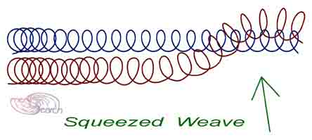
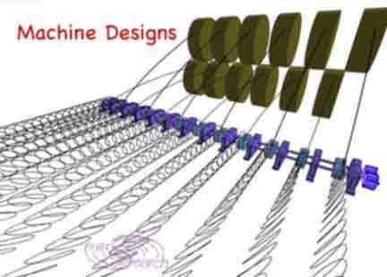
A hand made mesh test above is linked simply by sliding loops of one flat coil trough the loops of a neighboring flat coil. The 7 flat coils shown above could be formed simultaneously and "squeezed" together. The picture below shows a workable bending pattern which causes a flat coil to spread in a linear direction. Beginning with a "relaxed" (un sprung) coil of stiff wire, bend as arrows direct. Upon release, all 22 turns will offset the next turn in linear fashion. The same offset can be made with a cam or like mechanism, for continuously fed flat coils. The result is comb like in that the more pointed side can easily feed through adjoining coils to create job site meshes, of "endless" length. Plastic filaments may need a little more mechanism to "weave". Steel wires might weave with simpler action since wire is stiff enough to push through loops, as compared with plastic/ textile filaments.
(See some additional notes on bent coil
effects, click here).The remainder of this page will summarize experiments
with MIG wire coils, (in do-it-yourself" style). In short, new
tools would help. Most ferro cement builders buy tools and materials off
the shelf and hate to sacrifice time on experiments like these. Marketers
should think about this new market potential. Compound curved, ferrocement
building techniques are becoming discovered and demanded in the market
place. Superior reinforcement could compete with older products. Great
talent is networking on the web today and clients are bound to hire and
generate demand for provable performance. Whether the experiments here
foretell a worthy gamble for a manufacturer , that is the question. (To
be or not to be.)
Wire Handling & Unwoven Mesh
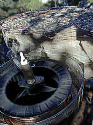
A continuous flat helix can be fed from an ordinary spool of MIG wire. However MIG wire tries to relax itself to a much larger radius than it's spool. It can twist into messy balls so it needs controls. Therefore methods to handle and use it in the "tensioned coil condition" were investigated. Finding the least labor intensive method to use welding wire for ferrocement was the objective. Composite reinforcement could also use this flat coiled wire reinforcement. First a stationary spool was considered. The rim of the spool impedes feeding of a flat continuous helix. So rim removal was tried with mixed results. Unpredictably, too much wire comes off all at once which is hard to handle. (Especially one day when some kids helped me;-)
A way to remove rims was tried. Router was pivoted in the center sleeve of
MIG wire spool. The pivot guide consists of an ordinary washer which happened
to fit nicely in the spool sleeve. This pivot washer was welded to a piece
of metal and a screw which fit into router's set screw hole. By tuning
this screw the cut radius was adjustable. The router was set to a comfortable
depth to cut minimal plastic (needed to cleanly remove the rim of spool).
With spools on ground, bent steel rods were stuck into ground. This helped
keep the stiff welding wire from springing out of control. While the stiffness
of welding wire is desirable for building, it is hard to handle and this approach
demanded too much skill in handling.
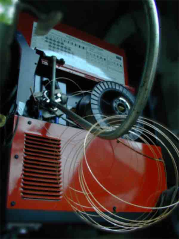
Next a commercial wire feeder concept was investigated. A method which feeds
bulk wire to industrial welding systems. It uses a spinning "eye" or
tube to extract the leading wire edge from the spool without tangling.
An improvised rig consisting of bearing, arm and eye was pieced together
and turned with a cordless drill. This experiment did not improve wire
dispensing. (However it the essence of it appears great for uncoiling very
large and heavy spools of wire to feed a factory welder).
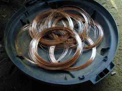
Next some pre-stressed coils were
investigated. A mig welder was used to "pre-bend" wire so that
it would not try to straighten itself. The "pre-bent" wires are
easy to use in cement. (Welding gas turned off and electrodes unused, just
the drive was used). This produced ample bundles of relaxed wire coils. The
coils are easy to apply in wet cement. The
rings made so far with all this experimentation can be viewed at this link.
The MIG wire drive is a well developed mechanism. This drive can be used for "bending" and
un-stressing coils but somewhat redundantly. If stress free wire was demanded
by the market, the original fabricator could bend it while spooling it. For
MIG welding purposes, every manufacturing effort is made to keep the wire as "straight" as
possible. (So that it will push through the MIG hose and gun easily).
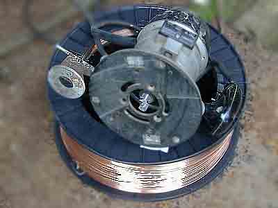
Presently a flat spiral feed is being studied which lets gravity drop a few
turns off of the spool and on to a "flat channel". The spool
is supported only from above. This system works fairly simply as so far
described. A few turns are easily and quickly extracted after cutting from
spool. Once removed from channel, the flat coils must be held firm to prevent
wild unraveling. A few turns are usable but many more turns impart advantages
to ferrocement.
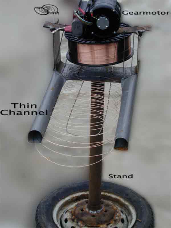
Continuous, non stop flat spirals are possible by adding a gear motor. (See
picture above). A motor was added to slowly turn the spool and let it continue
dropping more loose turns of wire into the flat channel. Flat coils are
pulled through the channel by hand. (For automation, rollers could replace
this hand work). The channel helps form the flat coil /helix and keeps
it orderly. A number of flat turns are grabbed between forearms and slid
out.
Continuous, un cut, flat coils reduce chances of wire ends sticking out of
finished cement. Fewer cuts in wire allow smoother, quicker cement application.
A continuous procession of flat turns can be placed into wet cement and
there be firmly embedded permanently. Alternatively, for the beginning
experimenter short sections can be cut and overlap other ring rows. similar
to the art of lapping fibre glass or papier-mache). Simultaneous cement
and wire application is conceivable from automatic machinery.
Future Possibilities
Continuous loop rings contrast with individualized "O" rings. Plain "O" shaped rings are self contained and easy to handle. Directly extruded ring manufacturing is desired. Pre manufactured rings of many sizes might simply be added to cement or concrete mixtures. However an introduction to potential manufactures has not yet been found. In the mean time, low cost prototypes are considered. The modern single phase MIG welder is an excellent starting point to build upon and develop an individualized ring fabricating machine. Wire could be made into variably sized rings from pencil diameter and up to many times larger. The interesting feature of individualized rings is that rings can become aggregates in specialized mixes. Concrete, cement and almost any composite may benefit from individualized reinforcement rings. An interlocking advantage beyond mere fiber is added. Rings extend tensile strength fully to extremities unlike fibers which offer reduced anchoring at fiber ends.
Possibly more interesting than individualized ring making is to make 3D rings.
Rings which entwine 3D space are suggested for study. Again the MIG welder
can adapt to 3D ring forming. .See some examples here--
Entwine 3D Space
The first two links include 3D reinforcement frameworks which "nest together" forming a chain linkage after permeated with cement. It is postulated that normal shrinkage cracking is better handled. Such frameworks benefit cold joint or slowly progressive building because moist curing is more easily assured. (Not having large frameworks to interfere with plastic curing sheet covers). It also hold potential for future power tools which could better mechanize construction.
While the welding wire as a primary reinforcement has excellent characteristics for ferrocement, simple methods of using it remain illusive. Agricultural wire offers much easier use but as a thicker gauge is less ideal than thin gauge welding wire. More effort will be made to show examples, here is a small example for the mean time. Here is another example of simple ringforcement using heavier wire.
Little is known about actual test comparisons between traditional reinforcement,
flat spiral loops and individual "O" rings. Rings appear to have
interesting test possibilities. As a low budget single handed developer,
I have very little opportunity to test the many ideas presented in these
www pages. The testing cannot keep up with my prototyping nor my conceptual
exploration.
The content on this website, http://harmoniouspalette.com, is placed in the public domain only as a free exchange of ideas and as a "hard studied wish to serve life". The author assumes no responsibility for the improper use of the concepts in these web pages, as all relevant laws of life and local codes should be verified and observed before any building or experimentation proceeds. discussion is welcome, please write. Bo Atkinson
Services ___Disclaimer ___Royalty Freedom ___About enersearch