As of 2006, the green
building movement had yet to appreciate some otherwise ignored architectural findings.
A
better conservation was implied by amazing results which were tested with government grant assistance. Various terms apply ie: Passive
Annualized
Heat
Storage,
PAHS, & Annualized
Geothermal Solar, AGS. Semi-buried houses hold many advantages for this more thorough and economical "green architecture". Otherwise, unburied
houses must be "buried" with piles of super-insulation. Minimalist-window- super insulating has achieved green popularity. However, it still depends on some heating fuel, (though a conserving amount of fuel). A demonstrated architecture here incorporates geology for heat storage, which stretches belief and skill. This page explores some potential applications. The incentive is fuller green living, bringing more daylight and scenery in for health, while not promoting world havoc for energy. This model is spurred by reported successes with underground houses.
Being a
visual person myself and an experienced experimental-builder, I was inspired to diagram how "geo solar heat" might be implemented in a traditional, above-ground house which poses difficult challenges for self-heating-cooling. I have yet to build AGS/PAHS, but have built thermal-storage and given lengthy thought to live observations. Semi-buried houses hold natural advantages to simplify and extend "green technology". Also, moving water in the soil would remove heat and ust stay away from heat stored areas.
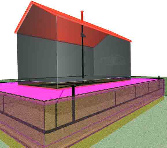
Following are schematic ideas on the possibilies.  An ordinary house might be retrofitted, by skirting a large mass of soil inside the building insulation. The purpose is to connect a large thermal mass to the house. (Cellar walls could doubly serve as a heat exchanger). Below, partly transparent views show ditching around the house for drainage and
insulation.
An ordinary house might be retrofitted, by skirting a large mass of soil inside the building insulation. The purpose is to connect a large thermal mass to the house. (Cellar walls could doubly serve as a heat exchanger). Below, partly transparent views show ditching around the house for drainage and
insulation.
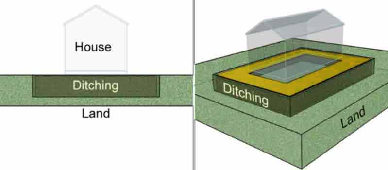
In addition to insulation, some form of earth tubes or pipes are considered to distribute heat. The pictures show a deep perimeter ditch. Pictured below, fourteen additional, shallow ditches radiate from house. The deep ditch must ensure good diversion of possible ground water, providing water-springs are not enclosed with-in the thermal mass, and a proof of concept deserves a much drier building site, despite that goverment supported research provided so much assurance about heat storage *.
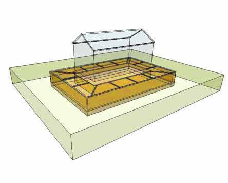
Drainage pipes are first placed at the bottom of the perimeter ditch, followed by insulation along with the heat distributing, larger perimeter pipe. Then, 14 radial tubes connect to the larger perimeter distribution pipe. (Ditches and insulation are covered and yard is made or restored, to divert suface runoff water in wet climates.) Furthermoe, rocky conditions present other challanges to study and compensate accordingly,m and in some cases abandone the objectives outlined here.
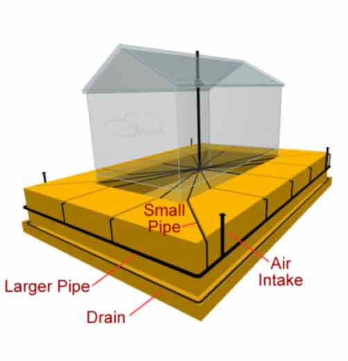
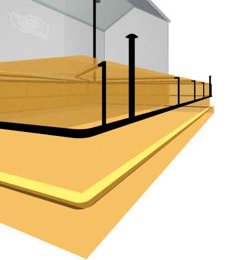
Additionally, four air-intake pipes are placed and other connections are made within the house. This model, for the moment, omits house-ventilation tubes which have been favorably reported in early PAHS work. Some arguments discourage house ventilation tubes passing through the ground, for fears of mold. As drawn here, the tubes isolate house air from heat exchanger air.
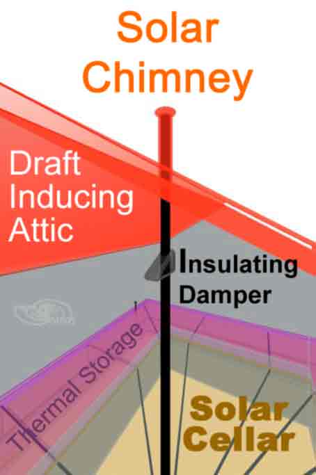
This modeling considers use of normal attic heat to help drive the whole system. Next shown, is use of the attic or roof heat, for inducing a natural draft. Roof construction can allow concentrated-solar venting through a chimney. A solar heated attic to heat a chimney chimney can produce draft equivalent to a small electric fan during warm days. I have decades experience using natural draft from my solar dome attic, (but built too early before PAHS to know about it. More on
solar drafts can be seen here.)
This model would need enough draft inducement from inlet to outlet. Summer air intake will "charge" (heat) the thermal earth-mass while tending to stabilize soil temperatures year round for a temperate climate. If additional fan power is needed, a solar-electric panel could provide the power just when it is needed, (during the warmest part of the day). An insulating damper could stop heat loss during cold periods, preferably a self acting type, (powered by a solar piston).
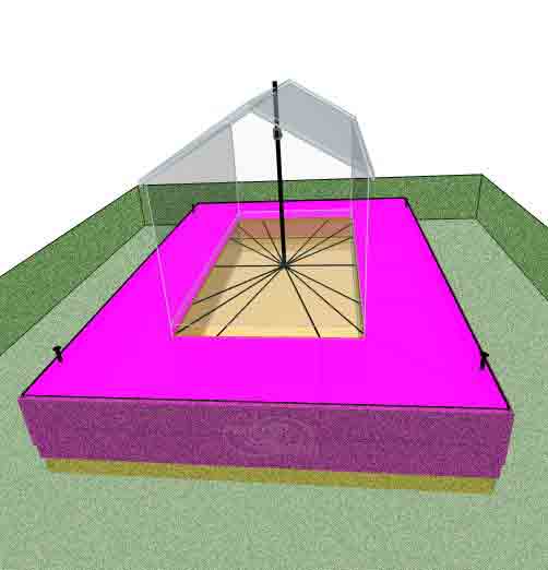
The thermal mass is connected to the house interior trough the cellar. It is blanketed (insulated) all around except for underneath (purple = insulation). While uneven pipe- paths are illustrated, in practice equal or balanced air flows are possible with manifolds and dampers added.
Such models could ideally be analyzed with thermal software to verify what kind of configurations are effective and most expedient for particular regions. Computer thermal modeling could provide us with valuable clues and findings. Good thermal software is generally available. I could not afford the software costs but do offer precision-3D-modeling to support thermal modeling.
A round layout example on this site: Branched U-Tube Thermal Distributor (designing an earth-tube installation for a semi-buried home.)
Competitive
Concepts For Building Above Ground
Circulating Barrel Vault: Simple square and round floor shapes circulate an arched enclosure inspired by "Traditional Vault" Features
Square
Donut Concept.
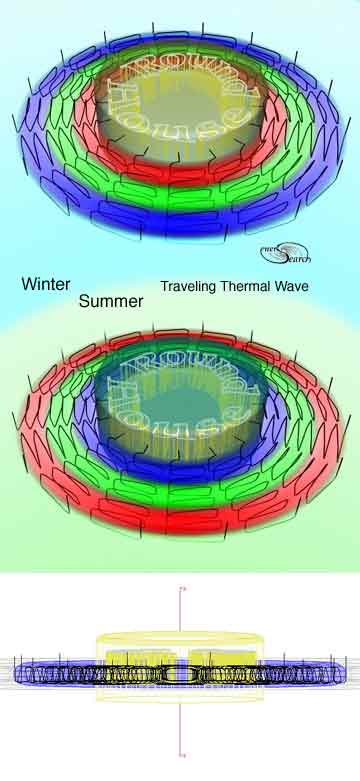
Next follows a concentric thermal gradient concept in search of best cost efficieny.
The drawing below shows the (exaggerated) thermal gradient wave in simple-coded
colors (blue=cold, green=intermediate, red=warm). A round house is surrounded by the concentric thermal wave. Air is drawn in through multiple, parallel tubes which are placed in a predominantly parallel-spiral pattern. A greater number of smaller tubes are proposed in contrast to the more popular notion of fewer-larger tubes.
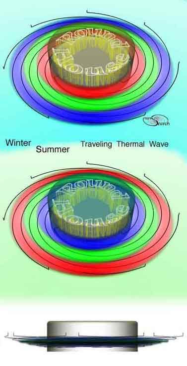
Snap shots of the thermal wave show the expected seasonal extremes. An alternative tube layout with radiating spirals is illustrated for larger buildings, (where the building circumference becomes to great for encircling spirals).
(These
second illustrated coils-above, have a potential for digging with micro-
excavators, from surface. Condensation
suggest a possible need for drainage holes in all valleys.)
Thermal
modeling would help greatly in scaling the system parts for optimum performance
and minimum cost. What diameter tubes would work best? (The software
generally recommended is FEA, Finite Element Analyses, generally not licensed
to small, pioneering efforts like this).
Consider ways to
force heat into bed rock through small drilled holes. A hollow pavement collector,
shaped to look like natural ledge can collect summer heat. A solar heated FC,(ferrocement)"mulch", sloped enough for heated air to flow to top of FC area, where it can collect, for heat storage. The picture on right suggests using water heated collectors.
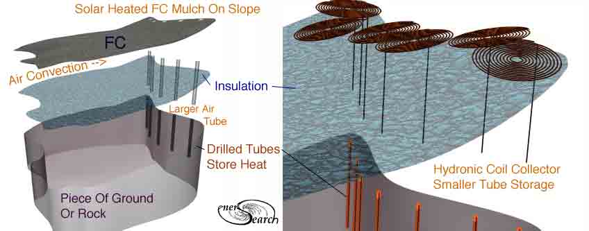
Another hot water,heat collector concept, click here for diagram. Here is a contrasting solution for use of water in a trickle down mode. Finally a 2009 project to employ this idea, an eyelid greenhouse.
* An early book on PAHS: "Passive Annual Heat Storage, was paid for by a US Government Grant.
I was happy to hear from a Swedish man
who offered a Swedish term "passive jordvärme". It seems the term "self
heating homes" googles some foreign language sites.
The content on this website, http://harmoniouspalette.com, is placed in the public domain only as a free exchange of ideas, discussion is welcome, please write. Bo Atkinson
Edited 2025
