A low investment, rapid prototyping, architectural production system is briefly modeled below. It could form highly complex castings, very competitively. Flat, composite truss production is demonstrated, but more complex forms can also be made, (one model at a time.) Many further potentials of buoyant forming are to be found at this linked-page
.
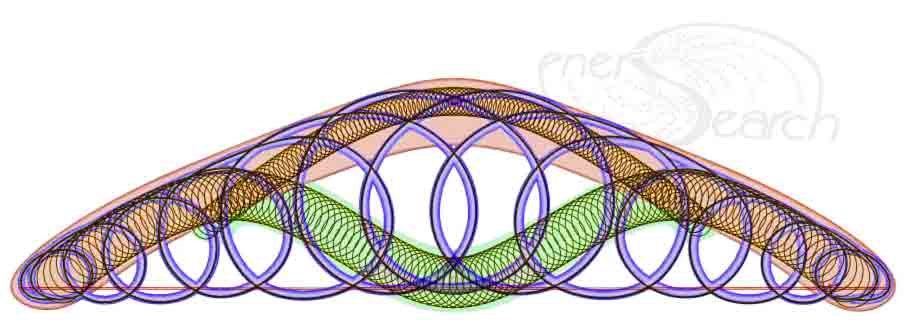
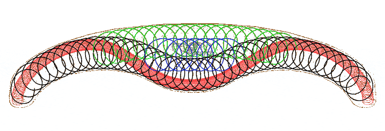
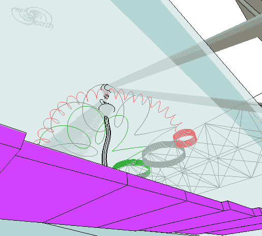
The visualization below depicts the recurve cable truss. This truss would be made with high tensile, flat coiled bars, wires or filaments. The flat coils would amply overlap. (Several variations appear on this website.) Colors are used to help distinguish the individual coils. The heavy black represents the largest coil. The red coil follows a "cable" path similar to a suspension bridge cable. This red recurve might be replaced by a simpler (set of) cable(s) or bar(s) as shown in some associated models. Ultimate specifications are the domain of engineers, (while the pages of this website are in the conceptual realm primarily). The other colors help distinguish the overlapping, continuous, coils. These coil or ring like reinforcements bind the entire truss together, after concrete or other cementitious composite consolidates the whole.
A birds eye view of a small fabrication facility is visualized next. A long pool or pond is used to float concrete or composite molding work. (The pool could perhaps be 6 or more parking spaces long). One end has a gradual sloped access for trailers to enter the water and be placed underneath finished work. The other end and the sides are modeled with vertical sides. Two silos are positioned near the middle beside the water. Across from the silos is a stationary mixer with bidirectional rotation for mix and dump. Only the drum is modeled leaving out the rest of mixer, as these are all primarily symbolic drawings. (Also, silos should be cylindrical instead of boxed). A work platform bridges the water between silos and mixer. A most effective layout method for shaping concrete products would use the antique secret of "Camera Lucida" but made digital! Here is a linked-page developing this system (named Cadmera which is essentially Camera Lucida for rapid prototyping).
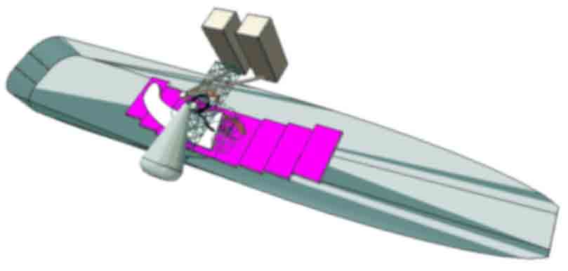
The ability to easily move a form work along both "X" and "Y" axes opens possibility to adapt this system for RP. (Rapid Prototyping or digitally controlled fabrication. More may be linked here on this topic which largely inspires the rudimentary work of this web page). Next below is a close up perspective with mixer drum on left and screw-conveyors coming up from silos, (to feed mixer). A funnel with flexible sleeve is guided by operators to place concrete to the floating form beneath. A flat beam product is being molded while it rests on top of floats (purple) which are well secured together. The reinforcement is essentially coils of wire which are fed on to the float from a simple platform.
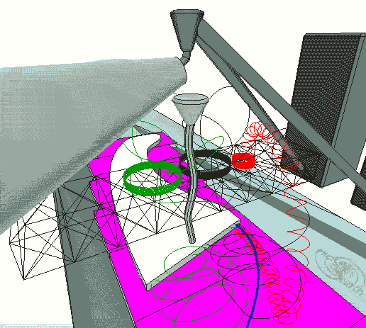
Much better coil dispenser designs are available, but the very simplest form is illustrated here for simpler understanding of the system possibilities. The wires are colored only to help distinguish them as they are continuously fed with the concrete extrusion. Overlapping, coiled reinforcement is a key element for "instant" and economical fabrication. A system named Ringforcement can greatly enhance concrete and ferrocement production. The white at center is the truss nearly half formed. Next below, the operation is viewed from under water, only to see more view angles. Forgotten in the picture are floating beams underneath to splice together the float sections. When floats are properly thickened and secured together, the extrusion process will proceed with negligible tilting, which will not adversely effect the process.
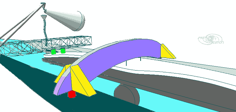
Positioning the loaded float will require very little power, which is a primary advantage of this forming system. Moving heavy products around would require only overcoming the inertia with simple levers, lines and tackles which also control the extrusion progress. After the forming process is complete and the product sufficiently hardened, it can be placed on top of a trailer, for delivery or storage. The next picture depicts the trailer under water. The finished work has been hung from a lifting- arch (light blue). After the truss product was hooked to the arch, water level was dropped, (perhaps pumped to an adjacent pond). The floating platform had been removed before the trailer was rolled in. Two green weights are shown as effective means to balance the product during the loading operation. Screw or hydraulic jacks (red) are used to drop the product gently on to trailer. (More arches may be deemed necessary for long products. Please bear with this schematically simplified presentation)
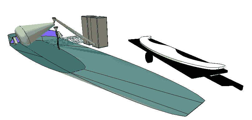
Next below, the trailer is pulled out of water at far end of pool.
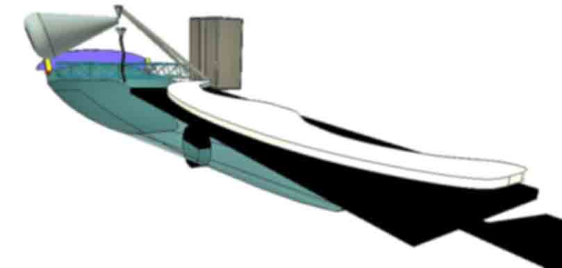
Finally, out of the water, the recurve cable truss product is parked. It is now ready for engineering and for development! Spammers: Get a life, try harmony!
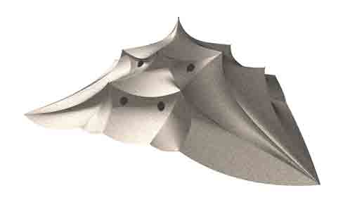
A recurve suspension vault which features the modeled truss can be found on this linked-page: A further quick example of more complex shaping is visualized below. It is a roof system inspired by the structure form called tensegrity, where rigid and supple forms work together. The original model was posted on this linked-page. Swoopy geometry is fun to solve and this author would be glad to work out any customized requests.
Helical Reinforcing (Flat Spirals)
This writer could be entirely wrong but does think ECC and other structural technologies will benefit considerably from "ring shaped fibers" and annular reinforcements generally. Here is his original article published on the www (link). If only manufacturing possibilities made available. Simply change the geometric shape of the straight reinforcement member into appropriately rounded shapes. Note: ECC and Ductile specs do not mention tensile strength tests in terms of finished geometry variables, just flexural and compressive strengths of limited geometries. Tensile construction testing should include competitive, fully-formed geometries. Not that it is easy to design tests that are widely accepted. Yet the truest authority should continually update benchmarks which yield greater understanding. All such study is not far removed from reasonable concerns, not necessarily at least. Efficiency- interests are here to stay. Here to compete strongly. Here to demand safety through an enlarging paradigm of harmony.
The content on this website, http://harmoniouspalette.com, is placed in the public domain only as a free exchange of ideas and as a "hard studied wish to serve life". The author assumes no responsibility for the improper use of the concepts in these web pages, as all relevant laws of life and local codes should be verified and observed before any building or experimentation proceeds. discussion is welcome, please write. Bo Atkinson
Competitive Concepts For Building A Green Roof Home With Hanging Garden Arbor
Square Donut Geometry - Disaster Resistant Structure
Does a dome on top of a cylinder or box have or deserve a distinctive term? I see that the word "cloister" works for square and perhaps poly segmented dome-vaults. (Google Images show some.) Am I missing something more here? How about a non english term from any language? anyone?
A Turkish person wrote:It is, Mukarnas or Muqarnas. The root-word "karnas" is from Ural-Altaic language group and ancient Turkish, still speaking by Yakut Turks at Yakutsk region in siberia. "karnas" means = to(cause to)stand out....beyond an edge or surface.
The words bring up nice architectural pictures on Google Images: Mukarnas ...&... Muqarnas