iNormal cement
shrinkage and settling can adversely compress along reinforcement lengthwise.
Shrinkage along immovable steel will crack cement. Design
strategy is considered here, to minimize shrinkage cracking by certain, particular
means, (in addition to other means better known to the trades).
1. Surface mesh which fragments accumulative shrinkage.
2. Pliable aggregate to further diffuse crack stresses.
3. Gravitational compression of convex roofing surfaces,
or natural-settling as post tensioning to compress concave
surfaces.
1. Short spanned
reinforcements in structural skin or surface mesh can distribute shrinkage
widely. Multiple overlapping spans can maintain tensile integrity
as does a chain. Cement between otherwise unlinked reinforcement rings completes
a rigidified chain effect. For example high tensile welding wire could provide
the mesh reinforcement instead of more commonly used commercial meshes.
2. Rubber crumb or other pliable aggregate will further diffuse shrinkage
stresses at very small scale. Cement medium may help prevent rubber breakdown,
however the micro segmentation should still prevent accumulation of crack
stress.
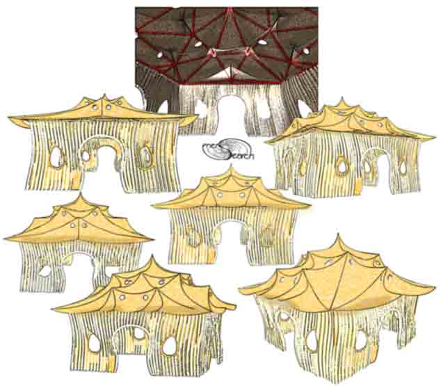
3. Gravity and post tensioning can be used to relieve shrinkage cracking. An
example is the convex vault or dome having it's own weight compressing it's
own surface. Below is a concept for compressing convex roof surfaces . The
outer roof surface is tied through flat helix reinforcement to a tensioned
bar
or wire inside, (at bottom of rafter or truss).
A conceptual, tensegrity rafter or truss plan is ferrocement, (shaded blue). It's geodesic layout is seen in the top drawing. The simplified cross sectional plan proposes a tensegrity effect. The upper and lower blue curves represent heavier wire or bar along which are spread the thin line blue helix trussings. The helix is pulled, spread and flattened into wet cement to form a curly mesh truss. The red represents the main tensioning member and the yellow highlight tension zones. Post tensioning these yellow zones is proposed to deflect surface stretching away from peaks and to compress valley surfaces. Tension members, (red and yellow), could have sleeving, (or external placement), to allow self tightening and slight vertical movement at yellow zones.
Each rafter- truss can be built while hinged 90 degrees. This to allow cement sandwiching and ramming of tensile members, (with clean, rebound free cement application). Preliminary testing confirms that ferrocement can built flat and hung as if on close line. Twisty wire bundles might perform well as permanent tensile members and as low cost post tensioners. More on roof sheathing may follow here in future. Means to reduce surface, shrinkage cracking do not necessarily imply cementitious roofing surface. In temperate climates, a variety of coatings or toppings might be considered (and benefit advantageously from reduced surface shrinkages and the thin characteristics of ferrocement.
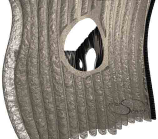
The corduroy walls above have flexible drain pipe cores, (black PE plastic). These are formed into pleasing curves. A variety of reinforcement strategies and pipe sizes might be considered. The hollow pipe may serve as solar collection or deflection and/ or insulation space. Hollow corrugation also offers 3D structural rigidity if cementitious material completely surrounds pipe. A variety of mixture amendments, (eg: reinforcements) can be used trading off mass for material performance. Hollow corduroy can save labor on highly unique curve work where that is a consideration. Flexible curvature potential is greater than with factory formed meshes. For higher load bearing walls, solid corduroy wall forming is equally flexible to form.
Pipe can be strung together on the ground or on a patterned form, (strung like a necklace piece). Patterned form would hold shape until cemented at least one side. A partial tilt could ease cement application, hinging the the remaining degrees into vertical position.
Ring reinforcement generally implies both "O" type individualized rings and also continuous, flat spirals. The continuous flat spiral is presently used due to it's immediate adaptability for low budget experimentation. Continuous loops of wire widely overlap themselves allowing the cement to penetrate and bond numerous linkages between. If variably sized "O" type rings were mass produced, then a very exciting new admix would simplify labor. Such "O" type rings could be manufactured economically using steel wire or other filament materials such as cement reinforcement fiber materials. Plastic or steel "O" rings as aggregate are a conceivable possibility. Rings deserve strength test comparisons against straight fiber reinforcement. The purpose would be to more fully benefit from tensile properties of strong tensile materials. It is expected here that ring geometry significantly increases the reinforcing efficiency of filaments or wires.
Too little is known about actual test comparisons between traditional reinforcement, flat spiral loops and individual "O" rings. Rings appear to have interesting test possibilities. As a low budget single handed developer, I have very little opportunity to test the many ideas presented in these www pages. The testing cannot keep up with my my conceptual exploration.
The content on this website, http://harmoniouspalette.com, is placed in the public domain only as a free exchange of ideas and as a "hard studied wish to serve life". The author assumes no responsibility for the improper use of the concepts in these web pages, as all relevant laws of life and local codes should be verified and observed before any building or experimentation proceeds. discussion is welcome, please write. Bo Atkinson