2008 efforts in glazing wavy arches follow below. (Earlier building progress is here). This page is a proof of concept. It studies: How customized, compound curves be accurately measured, recorded, transferred and then, finally how would we control cutting and fitting of wavy glazing? Here is a method using a low-cost digital camera and a lap top computer. It loosely applies the principles of a method called "camera-lucida". A 2d technique which was recently re-discovered from lost secrets of the Renaissance painters of Europe, (centuries ago).
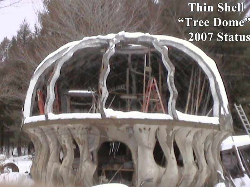
These principles may be applied to building in 3 dimensions, almost in a reverse order. Instead of producing 2d paintings from a live 3d subject, a 3d structure is installed by following 3D design plans. A lower costing method to build large sculptural structure, involving acceptable accuracy, has resulted. The traditional methods of tracing shapes as in traditional wooden boat building, would be extremely difficult for the glazing job in the picture below, (picture was taken in the winter of 2007).
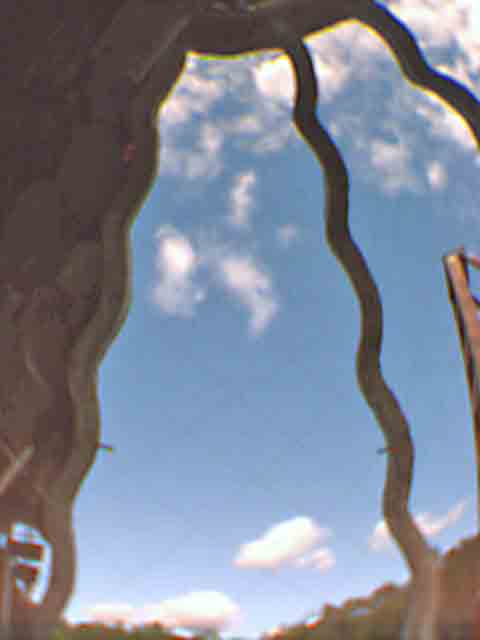
Confusing enough? Here we have compound curves and material sizes exceeding the human arm span by many times. We have unpredictable gusts of wind, some climbing incentives not to waste material due to inaccurate cuts. We all have human time constraints but i accepted the loss of much time in searching for pieces to my puzzle. I, (Bo Atkinson), committed myself to researching and experimenting with my techniques which i have generally named "cadmera". (The method described here, started on my "cadmera" web page.) Of the various efforts tried, some of my preferred methods follow, (for low budgets). (My pictures are blurred to speed access over the web, as many www visitors do not have high speed access.) First a digital camera and wide angle lens are positioned to record,(digitize) a view of the large opening to cover.
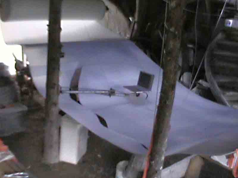
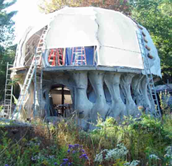
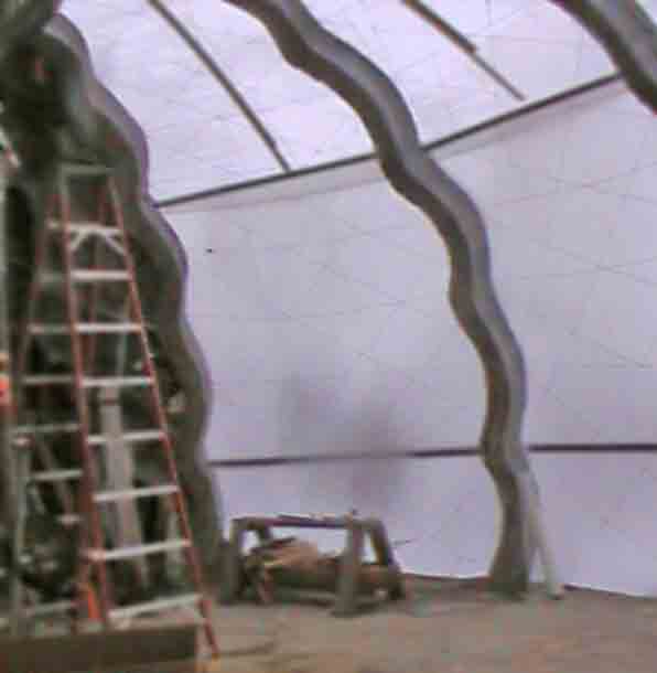
Picture Above- Summer 2008-- The opening to be glazed was camera-shot with a very wide angle lens. It was centered and each corner of the opening was measured from the camera using a 10 ft pole (3meters roughly). The camera was repositioned several times to find a position where all 4 corners were roughly the same distance from the camera. Ordinarily, wide angle lens introduce distortion. However, my surface to measure and define was part of a curved dome surface. Therefore, each part of the surface to be fit was roughly the same distance from my camera. This reduced my margin for error, but challenged my limited resources. (Yet my mind's advocate also argued that wide angle distortion of a live view, could otherwise be compensated by use of perspective matching views built into design software). (The wavy i-beam and "beehive" construction methods are further detailed here). The installation site, (summer 2008) appears below-
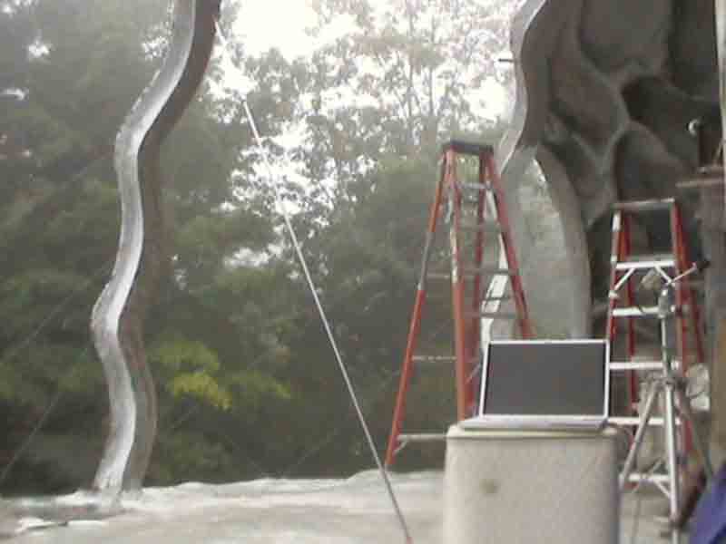
Picture Above- Plastic glazing was to be fastened to the ferocement wavy beams. A layer of softened cement, "papercrete" was applied to the outside surface, to hold fasteners. Unfortunately the mix was inadequately time-tested. The mix continued hardening over a 2 year period, more than expected. I should have studied that mix ratio and method of application, much closer. Unfortunately, i might have to remedy the fastener problem further, but later. I can live with another error, given the bigger imperfections of our world at large.
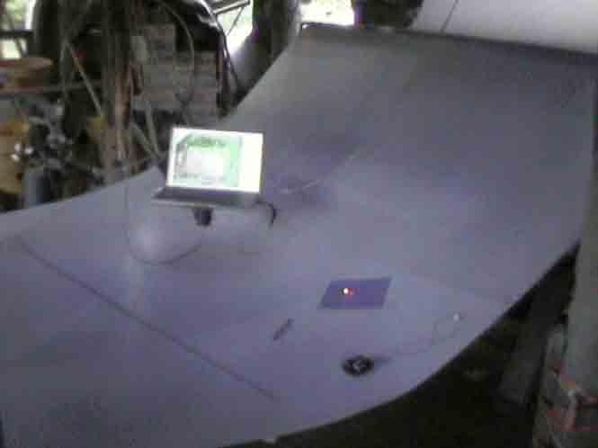
In picture above, the 10 ft pole is seen leaning against the wavy i-beam. This pole was used to position camera, equally spaced from all corners of the intended cut. The laptop is seen to the right, with the firewire "Fire-I" camera mounted on a tripod. The morning is foggy, reducing chances of lens exposure from direct sunlight. Besides, my slow progress demanded dawn to dusk discipline. Next picture below, the camera is mounted above the first floor, aimed downwards, through an atrium.
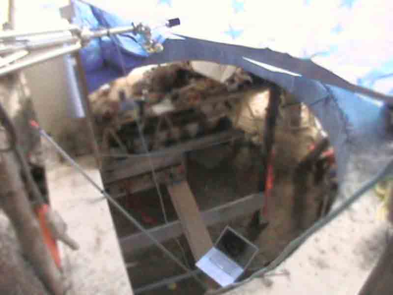
Picture Above: The tripod was simply propped horizontally. The lap top computer can now be seen down stairs on the first floor. Simple boards will provide a makeshift cutting table. The next picture views the setup as viewed from the downstairs.
In picture above, we see my bulk roll of plastic glazing material. This is double layer, corrugated, translucent PE plastic, similar to milk carton plastic. The "cutting table" has been arranged to hold the rolled out plastic in somewhat of a catenary arc to match my dome shape. This will assist truer measurements. The camera optics on the cutting table are identical to the camera optics when viewing the target, installation space. My lap top computer is placed on a hinged arm which i custom welded from surplus materials.
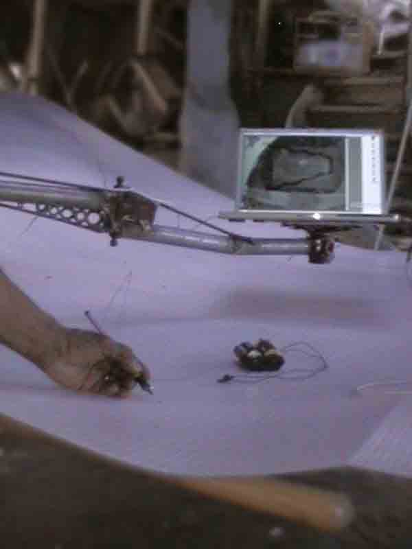

The importance of a movable PC is that it allows me to layout large cuts and "trace in reverse". Traditionally we would place our tracing paper above the source image. Then proceed to trace with pencil or pen. Digitally, we can view a source image in a PC, physically above the paper (or plastic sheet in this case). We capture live video of our tracing-hand in tracing action. As seen on the laptop image above, we simultaneously superimpose the saved picture of the opening to be glazed. (Same image as second picture from top.) We follow the superimposed pattern with our tracing hand, viewed through a connected video camera. Superimposing an image is achieved with a software which can render a chosen application-window semi-transparent. I use Unsanity brand WindowshadeX with my Mac G4 laptop in these pictures. Unfortunately, semi-transparency somewhat blurs the scene and reduces visibility. An art we therefore must suffer for, given current software standards. Fully transparent window backgrounds are apparently not available, to my knowledge, as of 2009. Ideally, a powerful design program like formZ would offer transparent backgrounds as an option for a design window. Real world construction could then be guided directly without time-consuming layout tasks. Real world construction projects could be guided directly through a visual design program. Computer-accuracy in layouts, is therefore offered to the mind's eye. Time consuming layouts with measuring tapes and marks, need-not burden building budgets. How much does layout work cost? In custom work, it costs a large amount. Mass production benefited enormously by avoiding custom layout time for each incremental production step. Customized building or production could likewise, hugely benefit, if transparent design-windows are made available.
Dots are here plotted first, as my equipment is far from optimized. (Compared to a better product-package, such as a marketable cadmera system). In fact i wrapped my tracing hand in black cloth, so that it would show up more clearly, while viewing my live video. (Black contrasts well against the white plastic sheathing material and through the cloudy-semi-transparent window backgrounds.) The video wire plugs directly into the computer, a video software for Mac called Security Spy. An optional method also has worked, though requiring too much user-effort. My design software, formZ, allows me to display images as a "rendering effect", ( or as "changeable scene" backdrop). Unfortunately, perhaps, design software investors think that solid color backgrounds are wanted exclusively. Not so, if i may say so. Fully transparent backgrounds, could spawn new progress in custom building. innovation could better prosper. Eventually the "measuring tape" could well evolve into a computer connected camera device which greatly simplifies a builder's layout tasks. Such a new device of the future might come in the form of goggles or look trendy like sunglasses. Perhaps a game company will first build something like this, for entertainment proposes, as markets need large groups of buyers, (and innovators are few in number).
I perhaps should study and learn UTube posting-- Instead another view of the cutting set up is added above. Note the 10 ft metal pole lying on the boards. It is used to verify that the live video camera above is well centered. Checking the distance between the video camera and the projected trace to be cut, assured me of acceptable accuracy in the overall process. Next pictures shows the tracing process--
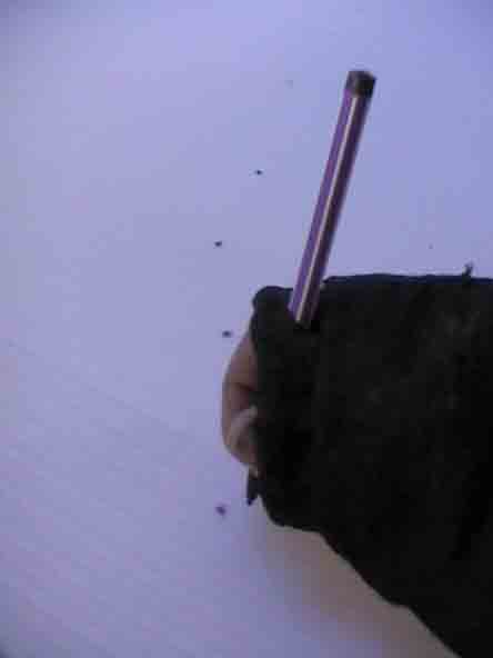
A sun shade curtain was used to improve laptop visibility, (pictured above). Note that the plastic is rolled out and rests on props, to impose the dome's curvature. A darker piece of paper, with a hole cut near to center, is seen with a bright spot. The darker paper improves the visibility of the spot, (on a PC screen). The bright spot is a very simple LED light bulb which is powered by some batteries. At the present time the LED is misplaced, but if people encourage me, another one can be wired together and photographed close-up to see how simple it is to assemble. Ideally, the cutting tool could have the LED light near the cutting point. Thus a person could cut, following a pattern on the video screen.
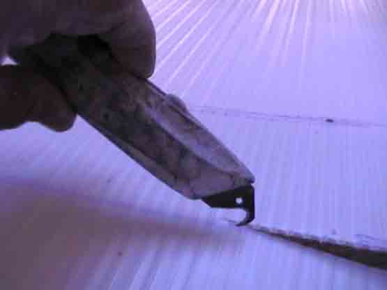
A simple box cutter is shown above, cutting through the double layer, of corrugated plastic sheathing. It is not a highly durable plastic, but with world leaders favoring perpetual war economies and war profiteers, innovation is too often left to low budget hacking efforts. Another sad thing is that today, even some American youths reply "what future", if encouraged to learn skills for the future. We collectively reap what was collectively sown. On the bright side, creative minds (on our world) are still permitted to encourage creativity, peace, harmony, productivity and happiness. Be of good cheer. Dome sheathing--
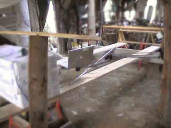
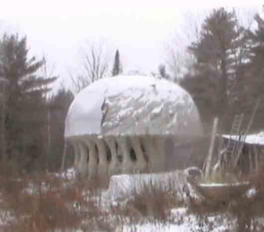
After each sheet was cut, (Autumn 2008) the section was tacked in place. (Yet my tacking job needs a retread, in all honesty). Instead of purlins, i chose to use a sandwich of galvanized wires. The wiring effort deserved better features than i provided. However it is conceptually practical and cost saving. The outcome was substandard but it was acceptable for an out-building. I cannot personally afford a boastful finish-quality nor a higher-taxed property. Better pictures should be added, but for now here is a winter-2008 picture, from outside--
One more fall/winter 2008 picture from inside-- Note the diagonal wire purloins, as well as some wooden batons for wet-snow loads. The sandwich of wires run in 3 different directions, so that the outer wires can apply more sandwich-bonding pressure in order to protect against the wind. More will be added to this site concerning translucency in buildings, in due course. I must also say that the corrugated plastic sheeting is not as flexible as hoped for. I also found some bad sections within the bulk role, (manufacturer defects).
Let me say, i justly should have, and did somewhat, expect building difficulties. Yet i also noticed unexpected insights. Such raw necessities may inspire new insights, which often are a consolation prize. Flat glazing or sheets, generally, do not bend equally well, upon two axes. Sheets are logically prone to planar bends over one axis only. Double wall glazing as used here is even more restrictive. Yet if a glazing manufacturer would willingly produce a "3d embossed texture" of one pattern or another, on one layer, (or perhaps both surfaces of double layered sheets) , then compound curve bending actually would work! Engineer an appropriate and simple 3d bumpy surface. The curves are exaggerated to emphasize the 3d texture.
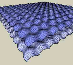
Compound bending should optionally allow contractions and stretches upon both surfaces, (as the builder requires). Another idea is here offered freely, (as i imagine "open source"principle recommends). So here was my insight, offered freely to the world: textured surface sheathing. Or a better bubbly sheathing is waiting for development. These will better conform to compound curves (and also planar curves). Call or write for more thoughts on how i would manufacture insulating, translucent sheathing like this.
I have been living inside a translucent dome (with further insulation partitions indoors). I have studied many aspects of translucent structures, for 30 years now. I have many ideas for such building and would love to build for clients or to build for research. I also love the idea of assisting manufacturers launch new products. Just ask. I'm willing to sign non-disclosure forms for new, original developments. Unfunded innovators can give away "inventions", in order to attract sustainable job level income. (Hire me ;) As this website implies, my skills span all levels of design and building, along with valuable insights for manufacturing.
If you are a designer or if you employ designers, have a look at bonZai 3d (the little software brother of formZ, currently as a free-Beta-download). The model above is rendered in the new bonZai 3d lighting ( which i would personally name "sunnyside" since the "sun" is always behind the point of view.
Here is my 2008 page on a domed greenhouse and glazing idea. The above glazing job is also intended for limited growing-space and also as a workshop space.
Here is a page on "self regulating" and essentially "free HVAC", implying annualized heat storage.
Here is a list of more pages exploring my structural concepts. Feel free to call me on the telephone, with any questions concerning my work or my service offerings. Bo Atkinson-- 1-207-342-5796 ~ Please start speaking when message-machine answers and we will pick up the phone when possible, as this method filters spam calls, (due to listing this number for so many years, on the internet).. Or email me at boa1@pivot.net Spam filtering blocks some of my email, but I do scan for new potentials.
Note: These pages are placed in the public domain and are furnished "as is". The author assumes no responsibility for the use or misuse of the concepts in this series. All pertaining laws of life should be satisfied, in building or testing my concepts or descriptions, as are posted on my linked pages.
All-Pictorial Menu  Menu With Text
Email comments welcome ~~~~~~~ ![]()