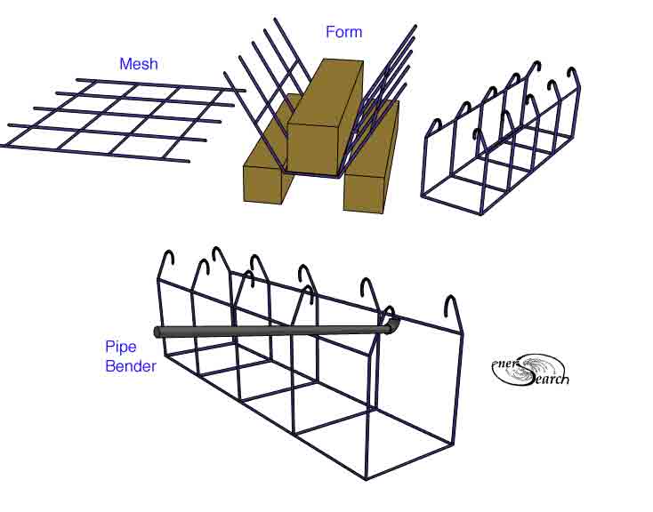
Concepts for interlocking units of WWR or WWM (welded wire reinforcement or welded wire mesh), provide construction forms and reinforcement for building walls. Simplified benders are illustrated above. Since the form and the reinforcement are the same material, considerable labor can be saved. Extra large aggregates or other many varieties of fill materials are all feasible. Pours from the top or masonry applied from the sides can suit the chosen mix. WWR units are simply slid into place and braced as deemed practical. While this kind of construction may best suit warm to moderate climates there are troublsome heat losses with metal ties. The same ties benfit wall stability, but the metal conductors pose losses, if the wall should provide highly-insulating qualities.
Insulation materials with or without cement can alternatively be used. Lightweight insulators like recycled styrofoam with a gradation of particle sizes could yield an economical core wall. Applying a thinner coat of high strength cement to ensure solid encapsulation of the WWR near wall surfaces is critical for structural integrity of wall. The hooks should become fully encapsulated in strong cement or concrete. Thus a distributed anchoring linkage forms from one WWR unit to the next. For more linkage, full length rods are also possible at top and bottom (green).
An optional adaption for ferrocement lining wall surfaces, (in picture above). Smaller mesh strips fit the form before filling. Other reinforcement materials might otherwise be adapted depending on availability, budget or user needs. Besides the ease of building walls, the distributed ties between inner and outer walls resists de-lamination of wall surfaces. Where concrete is used, there is a marked increase in "3-directional" strength of wall, ( 3D stability). A very talented builder and artist has independently developed a similar construction method in the State of New Mexico, USA. (Both he and this author seem to have come up with similar WWR application concepts at around the same period of time. This page was first started around New Years of 2003. Yet this author built his first insulated, dual faced mesh wall in 1976, but with wooden window framing for cross ties instead of steel cross ties.)
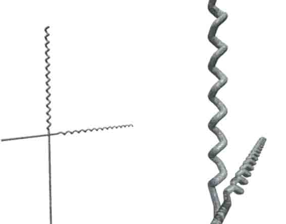
Optional bending arrangements for WWR follow.
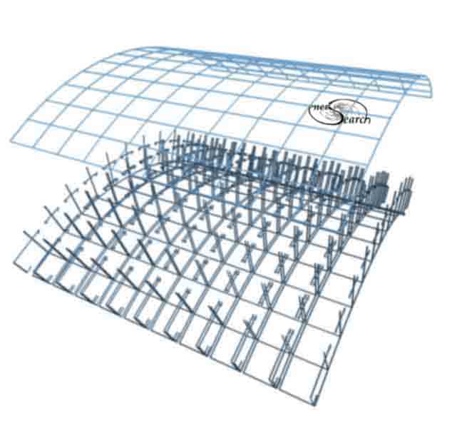
Vaulted layout above or similar bent sections in compound curved are illustrated in layout below. Excessive steel can result with compound curvature. In both examples, pieces of mesh are intended to push over tops to first welded joint. Then the protruding wires bent down. This effectively ties inner and outer surfaces together.
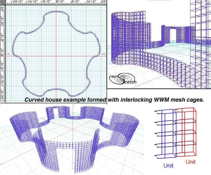
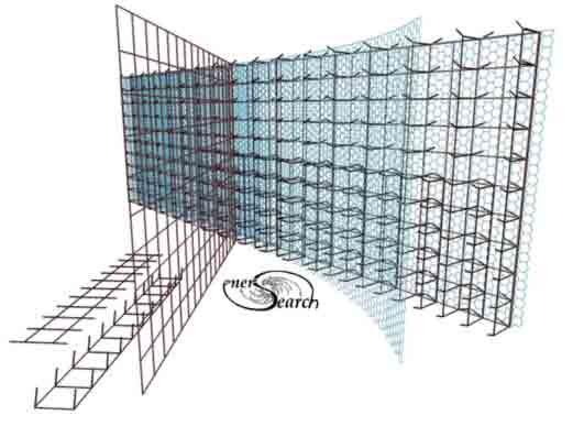
To avoid inefficiency , more efficient strategy employs individual "cubes" made from WWR. The cubes are illustrated in blue, graphic below. The red depicts the geodesic layout and the gray depicts a floor. One would reduce the amount of reinforcement used, to achieve better building-efficiency.
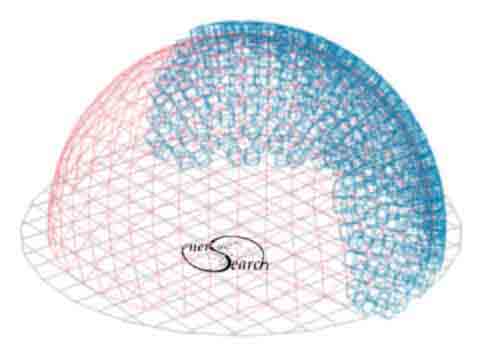
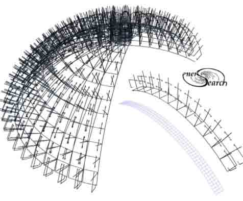
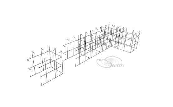
Geodesic layouts provide the most uniformly sized "cells" on highly rounded surfaces. The square grid work of WWR presents challenges when rounded surfaces are to be built. The illustration above provides one solution using"WWR cubes. Another example is displayed in the picture below. The WWR is cut and bent , making an empty cage, as a single unit block form. Ultimately this WWR unit , being encased in cement of one kind or other, can be considered a building block of sorts.
These "WWR blocks" are slid together to form continuously interlinked, chain reinforcement, (after appropriate encasement in cement). Next below is an example of forming a square corner. Among the primary goals is one to provide a system with features the advantages of masonry. A continuous block building process which additionally interlinks reinforcement without cumbersome, skeletal reinforcement cages, and allows compound-curvilinear structural wall construction.
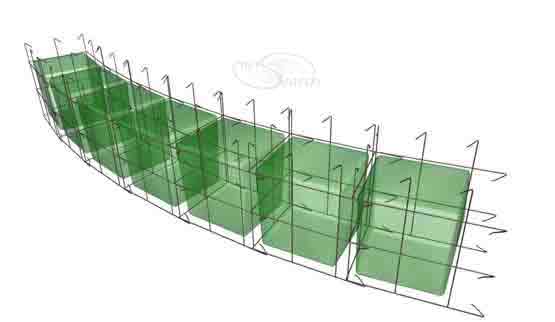
Next picture below shows the WWR blocks laid in a curve. The green blocks within are form work which slips out in a case hollow sandwich walls are desired .Hollow walls can be used to form ducts or be filled with other selective materials.
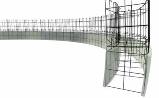
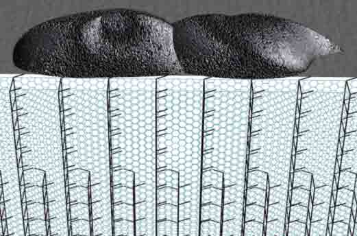
Two cement skin walls have been formed in the picture below. A second set of WWM cage-blocks are set in place.The angle of the second course of cage blocks is tilted so as to produce a dome like curvature. Once the WWR block has been formed, it needs no further on-site bending adjustments.
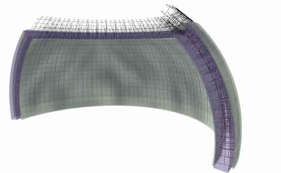
A section of a dome or a vault is next illustrated, (semi transparently to show the WWR). The thick wall-core here can be some form of insulating material or cement. High strength cement in the outer walls would produce a very solid overall structure, even with low strength, insulating cement/concrete in the wall core.
Another possible innovation is to make the WWR block ends "rippled". (Perhaps a hydraulic jaw and mandrel could do this and other bending and cutting"). The objective would be to develop some means of catching and adjusting the tilt-angle of adjoining blocks. To place and adjust blocks in one motion, then move expeditiously to the next block-cage to install.
Builder's Layout System ...Simpler construction routines are expected, which could translate to lower cost and greater construction- efficiency.
For a comparison, here is a page featuring interlinked "building blocks" which feature ring reinforcing in contrast to WWR.
When straight walls are made, addaptions of sheet WWR are applicable. Various methods can be adapted to tie together, an inside and an outside wall.
After mesh assembly and bracing, a small "shelf" may be added along top edge to receive poured concrete from a truck. The shelf allows less precision with chute placement, where pumps or better equipment, or where enough hands are not available to help. Sheet metal surface allows easy shovel handling and lets even one man handle large pours on a low budget!
Alternative ring reinforcement methods introduce elements of truss like triangulation which might offer better efficiency, adaptable to any surface curvature. Rings offer efficiency along with easier production possibilities and easier structure scaling. Descriptions of reinforcement structure using three axis ring reinforcement can be seen here (and the original ring-reinforcement here) More on rings for elements of framing in structures (click here).
For smoothing surfaces, soft rubber rollers are the easiest tool to use. Paint rollers do work except are unnecessarily absorbent and not so durable. A closed cell rubber with some degree of cushioning and minimally absorbent is best. Rounded roller ends like "cigars" can give less streaking on flat surfaces. Rolling two or three times, with several hours of concrete stiffening in between, gives easier smoothing, but hot climate poring would need more speed. See new details on rollers, click here.
See a rotary grinder concept for rendering waste styrofoam packaging down to aggregate.
The content on this website, http://harmoniouspalette.com, is placed in the public domain only as a free exchange of ideas and as a "hard studied wish to serve life". The author assumes no responsibility for the improper use of the concepts in these web pages, as all relevant laws of life and local codes should be verified and observed before any building or experimentation proceeds. discussion is welcome, please write. Bo Atkinson