A prototype idea for a vault forming system flips each vault. The reason for flipping an unwieldy vault is only to avoid later overhead plastering (and control the finished surface of ceiling). Most any of the surface wetting finish techniques could then become permanent ceiling surface. At the same time, a monolithically finished vault might be achieved.
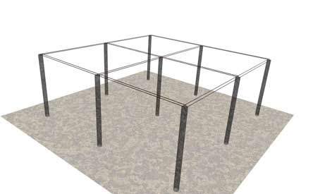
Above: Concrete pillars are braced in a square layout. Initially, parallel bars are part of the bracing and are left permanently in place to become part of a carry beam. These bars could have washers welded center and at ends, which then could latch on to studs protruding from concrete pillar tops, (for fast and precise placing). (Other required bracing is not shown in this preliminary modeling).
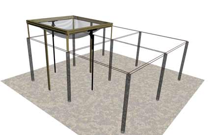
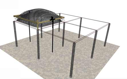
Next Above:The flipping form work is installed. The form surface could be mesh to become integral with vault or it could be fitted sheet rubber on temporary mesh framework. The model used 8 wooden beams to hold up edges. The beams are bolted to steel hinges which in turn are mounted on temporary poles (temporarily clamped to bars). In addition, corner "legs" give more needed support.
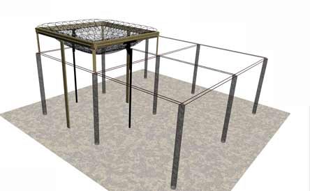
Next, the ferro-concrete or ferro cement is applied. This model shows how rings could be used for reinforcement. Presently, rings actually necessitate improvisation, for example by stretching out a coil of wire, (into flat spirals). Ring reinforcement theoretically will match curvature better than rigid meshes. Links below include more pages on ring reinforcement.
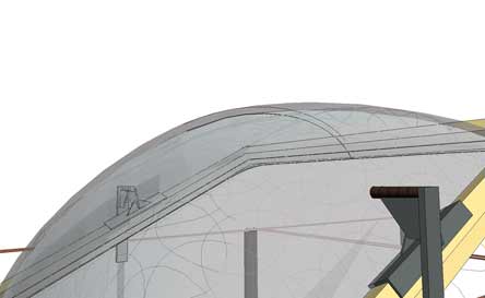
Next the "overnight cured" vault is flipped 180 degrees. Fortunately for CAD modeling, it was noticed that the wooden beams would not clear the bars! The angular alignment and wood thickness are too wide. Slimmer metal sections need to replace the bulky design in this model. (CAD Corrections might update this page in future). My solution would be to keep temporary support material well inside the open profile.
Given the mentioned clearance, the vault would next be held in final position. The four vault corners would be cemented to the four pillars.
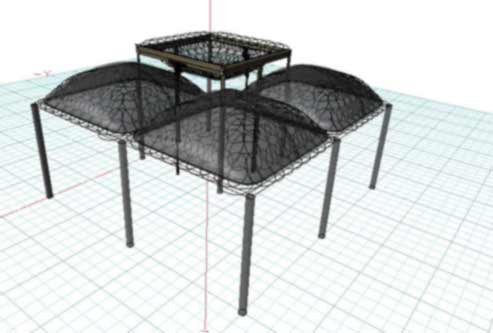
Continuing onward, the picture above intends to show 3 flipped vaults "welded" to pillars and one remaining form work. Yet to be shown is the "welding"or filling of the clearance-spaces left between vaults. This filling will also compose the main support beam between pillars. The filling would also depend on engineering considerations. Alternatively, multiple vaults might be formed simultaneously, given adequate budgeting for additional equipment and crews.
This forming system was modeled in response to a potentially upcoming project. . Visitors to this page are welcomed to pose questions or comments, neutral, pro or con. The potential project may or may not proceed further, perhaps at least to correct this model.
Another complementary system is also under consideration. Continuously fed, low volume, silo-fed, automatic mixing and pumping of concrete will be modeled and linked here. This minimalist delivery system intends to continuously deposit a slow ooze of concrete into form work. Furthermore, the ooze could also be automatically sprayed as the user places steel rings. It has been found that just a little wet concrete will successfully hold rings as they are placed.....A single person might then be able to concentrate on the fun of placing and finishing, since labor is saved. Easier production might be enjoyed for those on single handed budgets and where crew wages are prohibitive. A target electrical rating under 15 or 20 amps is hoped for using motors and controllers.
A exhaustive webpage on ring reinforcement is linked here.
While the welding wire as a primary reinforcement has excellent characteristics for ferrocement, methods of using it are evolving. Agricultural wire offers much easier use but as a thicker gauge is less ideal than thin gauge welding wire. More effort will be made to show examples, here is a small example for the mean time. Here is another example of simple ringforcement using heavier wire.
The content on this website, http://harmoniouspalette.com, is placed in the public domain only as a free exchange of ideas and as a "hard studied wish to serve life". The author assumes no responsibility for the improper use of the concepts in these web pages, as all relevant laws of life and local codes should be verified and observed before any building or experimentation proceeds. discussion is welcome, please write. Bo Atkinson
Comments were received on this idea. Here would be a further idea to check:
Hi there, you have some fun pages on the web, thanks.
On your idea of vault judo: I think that, so long as the frame is sized such
that lowering the vault onto it catches all the edges of the vault, it will
always be too small to flip the vault in the way you sketch. However, if
you flip it by opposite corners instead of the middle of it's sides, then
you can fit it through any size frame, just by raising it up a little higher.
Anyway, keep up the good work. If you find this useful, you can mention the
clarification as mine or not, as you see fit.
Warmly, Keith
--
Keith Winston
Earth Sun Energy Systems
Hyattsville, MD 20781
301-980-6325
Little is known about actual test comparisons between traditional reinforcement,
flat spiral loops and individual "O" rings. Rings appear to have
interesting test possibilities. As a low budget single handed developer,
I have very little opportunity to test the many ideas presented in these
www pages. The testing cannot keep up with my prototyping nor my conceptual
exploration.