Tetra- Isotropic Coil
Preliminary Prototype Testing
Bo Atkinson 2/20/2022
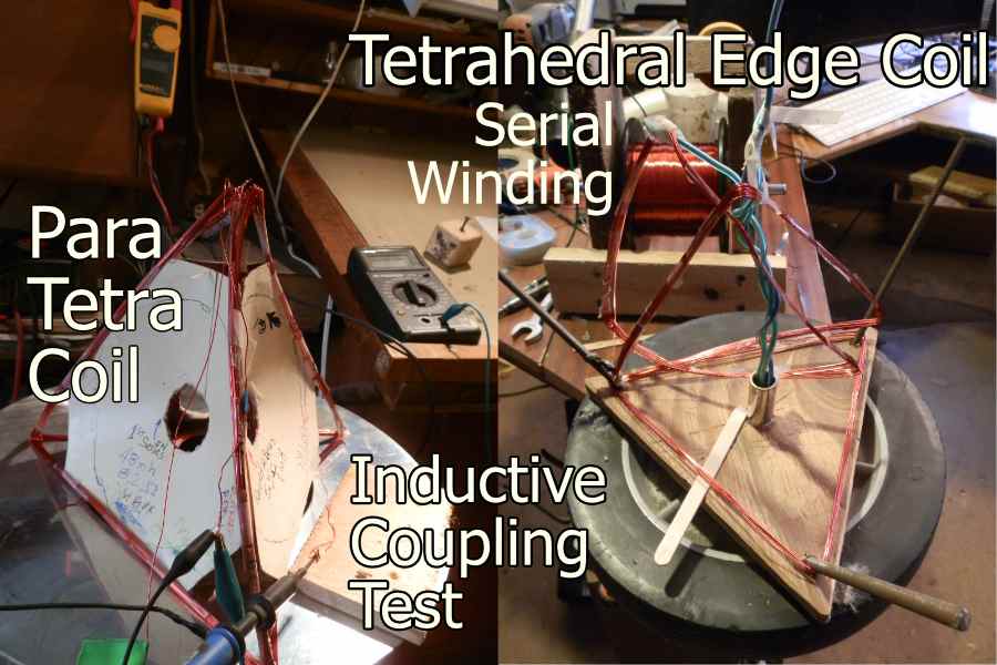
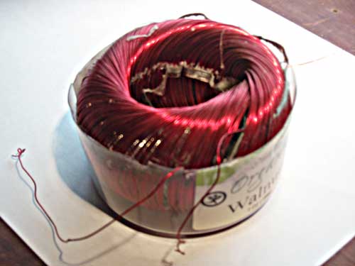
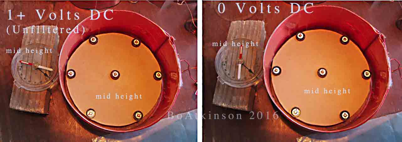
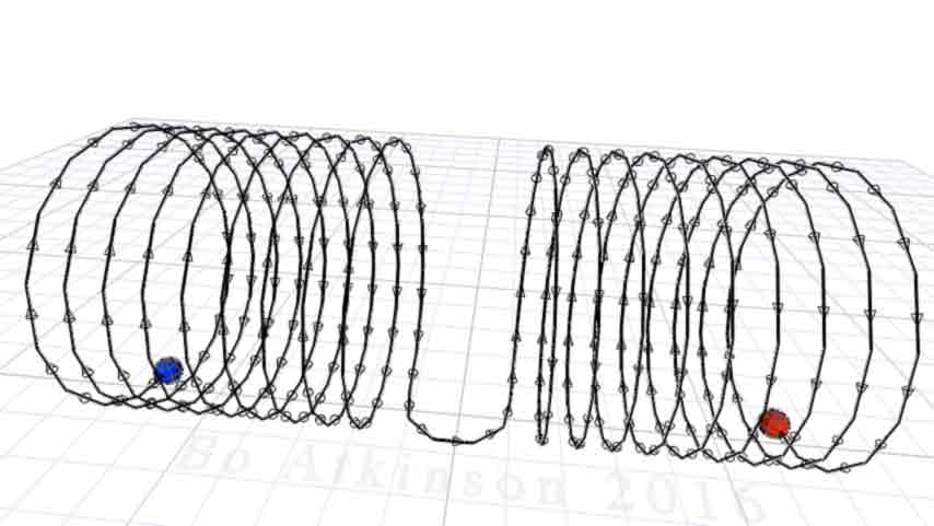
Animated 3D visualization above reveals the sandwiching of four conically shaped coils, precisely squeezed together into a tetrahedral framework and electrically connected together, to energize a generally isotropic coil. Whereas most electromagnetic coils maintain two poles around their structure, an isotrpic-magnetic-coil should dominantly radiate one and the same pole in all spacial directions. How evenly the single pole field strength will distribute isotropically, will depend on seamless engineering, especially at the vertices, (just to begin with). Below: A very preliminary, paper-backed, hand wound coil set, is generally tetrahedral, but with looser bundling on left, and a tighter squeezed bundling on right.
After powering up the tighter pressed coils, each face center was observed with a compass, and the tighter squeezed coil faces each bore the same pole, implying that an isotropic field overall had passed it's first test. Whereas, the looser bound coil condition on the left, which was tested earlier, tested asymmetrically, by comparison, with two poles evenly sharing four faces. Both serial and parallel connections were lightly DC powered, to observe variations of polarity, while the isotopic effect was satisfactorily observed with all four coils connected in series, after the process of improving the tightness.
Physical irregularities of excess distances between the four coils, necessitated the reconfiguration of better clamping or squeezing. The report on constructing and adjusting the isotropic coil prototypes continues first, and then a visual history of experimental coil geometries follows, describing earlier geometries which contributed to the objective of this experiment. Inducing dominant-directional-flow effects, gave reason to hypothesize isotropic field effects. The search for dominant field induction motivated the human energy necessary to carry through to this internet publication.
These preliminary models have presented some insights to learn from, before regrouping to attempt more precise construction methods. The asterisk * in the above photo refers to the need of closing all air gaps as tightly as possible, which may ultimately require 3D printed circuits to close gaps most-effectively. Hypothetically, by engineering better folding techniques, at the polyhedral corners, the dominant isometric field effect, will have a truer dimensional proportioning, well worth the continued efforts. This could determine whether micro and nano experiments with these geometries are worthwhile.
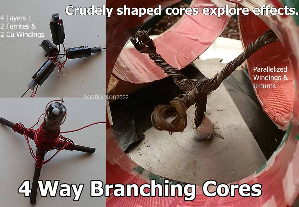
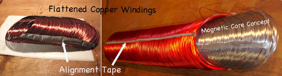
Above Right: A roll of wires was shaped and twisted into four branches, and inserted within three electromagnetic coils, (at least, and these were "split-cylindrically-parallelized-windings". Experimental configurations of magnetic branching effects will differ according to the center most bond of the four branching core parts. Magnetically modified cores pertain to subsequent alternating current experiments, (and are more complicated methods). So far my usual frequency sweeping experiments are prevented by failure of my old equipment. On the left above, are branching metallic and ferrite cores, which begin to explore various winding patterns. Below: Schematic of tested interconnections for electrifying tetrahedral coils, (and mostly the paperback tetrahedral coils).
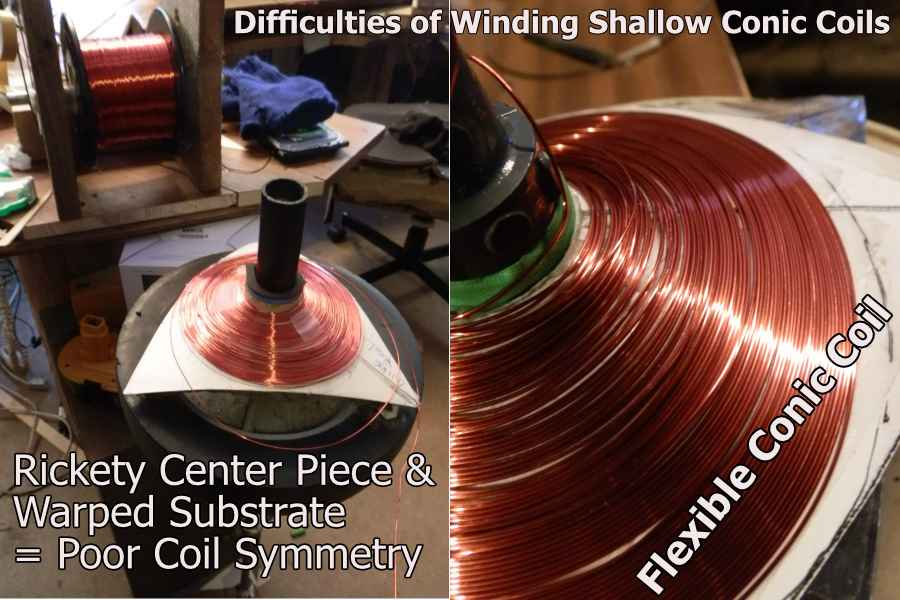
Both flexible paper and metal sheets were tried for preliminary making the conic coils. The initial efforts resulted in uneven surfaces where very tight spacing should eventually be achieved. The shallow profile is required by the partitioned tetrahedral framework. Upgrading methods by use of a lathe will eventually form truer conic surfaces, to improve accuracy of the winding surface and perfect the center piece. Note the loose windings, due to wobbling center piece, which resulted from uneven cone substrates.
Earlier experiments hypothesizing coil types, is reviewed further below. My (very old) oscilloscope and pulse generator are not properly functioning at this writing in early 2022, so that frequency-response tests cannot proceed immediately, but the polarity determinations and the task of writing this page were all together quite enough for a mere person to handle.
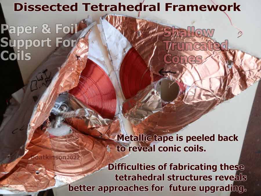
Physical dissection of the first paper-backed trihedral coil reveals difficulties of physical modeling, to attain proper alignments of copper wire coils. The actual coils were wound primarily upon "paper cones" to make use of "unfolded CAD patterns", to accurately fit the trihedral form, and the metal foil tape was to improve durability and magnetic characteristics such as diamagnetism-between-touching-coil-faces, (to be explained further down this page).The par-trihedral-coil is 3D rendered below, which simply omits the fourth, bottom coil.
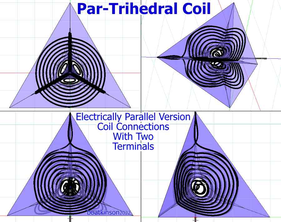
Above: Electrically parallel connections of three coils through the "top and bottom" of the trihedral framework, (which is a comparable framework to the tetrahedral-isotropic coil, except that the bottom coil is removed and the coil interconnections are not serial connections in this graphic). A natural application may pair up two trihedral coils at their bases to grow the family of polyhedric, isotropic field coils, (as projects may continue). Density of radiated fields and uniformity of surrounding field are here hypothesized. As many polygon types can eventually be built, with as many faces as may be wanted. (These 3D models might be well suited for finite element analysis software, (FEA). Laws of physics are preliminarily reaching the 3D CAD market, (price wise), but FEA is still not likely to be found flawless, nor "complete, for all of physics, nor for all of time".)
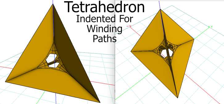
Internal tetrahedral coil partitions direct the one-way, isotropy, distributing the magnetic flow direction, of induced fields. Initial prototyping has vacated and rounded the tetrahedral center for auxiliary access to the isotropic center point and the electrical connection points. Beveling the central partitions in the 3D model above was to increase the central space volume, for other possible functions, but space like this might inadvertently oppose isotropy, because the internal tetrahedral corners present weakness of field containment, due to bending of the conductors. Traditional copper wire coils bear empty volume in between neighboring wires, and this permeable space might also pose electromagnetic leakage, which opposes the sought for isotropic formation. These possibilities deserve eventual, further examination, and possibly with fillers like diamagnetic bismuth. Partitions also integrate the coil substrate for physical support and for self capacitance of the coil overall.
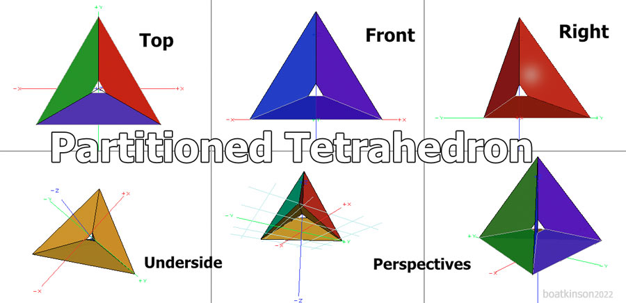
The internal partitions of the tetrahedrons, inherently provide an optimal parallelized magnetic alignment, hypothesized to enable isotropic magnetic flows, in a 3D, electromagnetic body. An alternative to wire coils are the available, manufactured "printed circuit boards", which will better enhance diamagnetic resistance between the tightly positioned conductive traces, even at sharp corners, (possibly). None are perfect, but narrowing down and blocking the stray magnetic leakage is an attempt to improve the isotropic field structure, and then ultimately, to open up studies of alternating isotropic field effects.
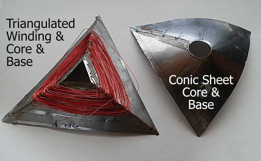
These coils are so far explored as round coils squeezed together and also as triangulated frame coils, (as displayed above and in two images below). These inductive couplings are initially explored only with DC currents and a compass, so far, , and besides we should note that the precision of magnetic bodies, (as prototyped so far), are not yet optimized. It is better to attempt better coil renditions and save up the preferable ones, before good test equipment is employed in this work.
There are multiple aspects to clearly differentiate and to fit into the above 2022 work. Combinations of combining clockwise and counter clockwise coil windings, into the tetrahedral frameworks, seemed ineffective, initially, as a method to avoid the piercing through, or worming-through of whole magnetic axes, all the way through the tetrahedron center. After the closer squeezing of coil faces closer-together, the isotropic effect took hold, with identical clockwise, CW, windings. (Yet the CW and CCW combinations pose interesting differentiations of effects, yet to explore further).
Alternating isotropic fields are considered most promising for an exploratory basis of "standing spherical waves", and the possible implications of understanding physicality, and otherwise for inventing useful devices which utilize isotropic fields in the human scale of existence, (possibly).
Before digital cameras and affordable 3D software, (generally this was before the 1990s), cruder hand drawing methods were attempted to study 3D flowing relationships of coils to be wound around spherical frameworks.
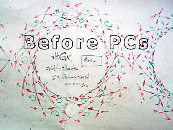
Crudely innovative attempts emulated aspects of woven baskets, to induce isotropically aligned magnetic fields. Electromagnetic models attempted to form multiple electromagnetic axes, in symmetrical arrangements of geometry. Subdivisions of electromagnetic windings, such as tracings of geometric edges of polyhedra which were then modeled in a variety of coherent forms, despite that crudity would obviously need much more eventual refinement, which would take up a lot of time in the long process. Tools, materials and equipment took me decades to acquire.
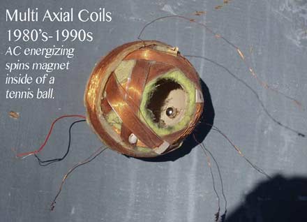
Early testing of coil resonation with limited apparatus of cheap signal generators and one oscilloscope, primarily noted inherent frequency harmonics, but the equipment range was too limited to test precise pulsing, and without burning out equipment, in case excessive currents were encountered with powerful resonance. The initially meager results nevertheless revealed the strengths and weaknesses visually, which inspired new workarounds to continue modeling and testing. This usually involved curvature of an axis, or specially situated axes. Woven basket artforms provided abundant conceptualization for coil experimentation.
Experimentation included concentric confinement of electromagnetic fields, by winding turns to form axes on the faces of faceted spherical forms as a complimentary approach to further integrate. Resonant timing of magnetic pulses were gingerly tested and hypothesized to rotate internal fields three dimensionally, and this provided a continuing exploration to aim for, over the years. Shielding from unwanted electromagnetic fields, by use of flatly spread coils of (grounded) wire had come to mind as a result of working up a concrete reinforcement system, (linked here). As shielding applied to architecture, it is worthy of investigation for the integrative economies involved.
Evidence of synergy was sought for, to identify compatibilities of concepts, and possibly refine them in new models. This work was fairly primitive in the kind of equipment available in a recyclers budget, and therefore it has always been largely hypothetical with limited physical modeling and limited electronic testing, yet the efforts always recommenced, in between making a living at other occupations. The conceptual progress also improved the spirit of an isolated rural lifestyle.
The budding flower-like petals represent core material for interleaved coils, which flatly enfold spiraling petals. There are some actual flowers which similarly bloom with inspiring petals. Disciplined conceptualization required tangibly replicable effects, which in part became increasingly possible with (affordable) computerized geometry after the 1990s. In fact software tools vastly increased the home based engineering power and the testing of build-ability, (and of detailing electromagnetic field visualizations).
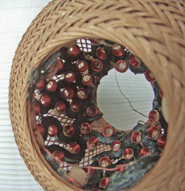
The basket above was used to position little hand-rolled coils, wired into series along a kind of windshield putty,. (sold by glass suppliers). It was more of a conceptual mock-up stage, without the parallelized-winding effect and without good alignment to a common center.
Folding of printed circuit sheets suggested possible construction of coil types, which might ultimately improve particularized fields, (instead of just one toroidal field).
I have had some good, double sided, copper clad sheets to etch but am not entirely sure, I could precisely align the laser print for etching, or align the folding process for the mutually inductive-coil-circuit-prints. Etching chemistry demands more study for me, especially with handling wastes ecologically. Prototyping shops charge a lot of money for this kind of work and I can understand why. Sharply bending the double sided sheets might introduce kinks or warps which affect magnetic performance.
Copper circuit traces would exploit the smallest possible soldering tolerances available for soldering tiny parts to a circuit board or sheet, of multiple leads, or conductors. This should allow for efficient connects of the coil traces after folding and or fitting together the 3D tetrahedral result, (or to apply this concept to form coils of other polyhedra as well). The drawing below is meant to represent continuous windings, and used scaled edges instead to save modeling time, because a well engineered version would take far more precision and effort.
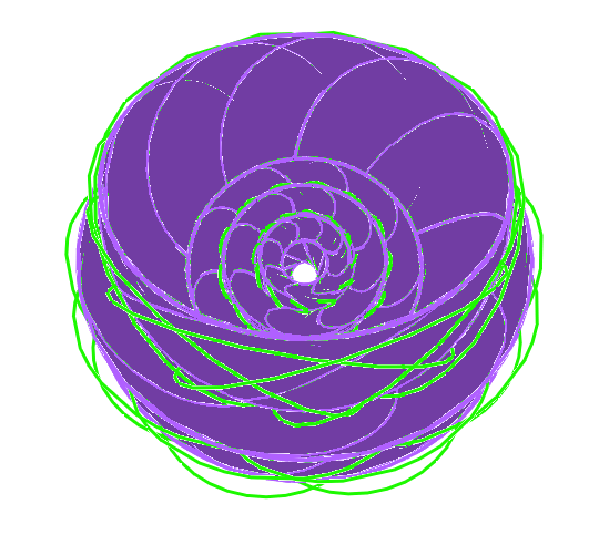
The spinductor below was another promising experiment, and it would also need better production facilities than my rural set-ups, to avoid unwanted irregularities, and this factor delayed it's prioritization. Varieties of 3D models followed nevertheless, as 3D software has efficiently worked out buildable geometries. The spinductor's magnetic flux structure (above), depicts enclosed, concentric spherical surfaces, where inverting onion layers serially and reflexively. This model is buildable with today's printable conductors and ceramic insulators, (given a facility devoted to efficient production).
The spinductor idea imagined magnetic reflex-fields in various forms. A well regulated spray-coating chamber would better insure this experiment's results, in an effort to evenly distribute and gauge thicknesses of layers, to balance the flowing currents and to insure proper electrical insulation. Various models of spinductors were posted here. This reflexive electrical path, (of electrically conductive coatings), would counter flow the magnetic paths within the insulating layers, (ceramics perhaps with magnetic properties to be added, ultimately). Here again a counter flow of magnetic currents can be tested or otherwise a single flow direction can be favored, (in the first instance with magnetically flavored layers, and in the second instance with minimally magnetic layers).
The above examples conduct electrical currents concentrically and isotropically, along a single conductor which narrows in surface width towards the spherical center, but the narrowing portion could be proportionally thickened to match the intended current flow. A concern about a possible unbalanced electromagnetic flow has also prompted the concept of individuating a set of strands along the concentric path, and eventually the idea of twisting these paths became easily generated with 3D apps, as displayed below. While the single axis spinductor suggests an orbital rotation, a multi-axis spinductor suggests 3D helical rotations. Possibly a modified 3D printer with a synchronized lathe, to turn the print bed, might enable a process of "3D printing" this specialized electromagnetic coil, however printable conductors still offer limited electrical conductance, (bearing far more resistance than copper wires).
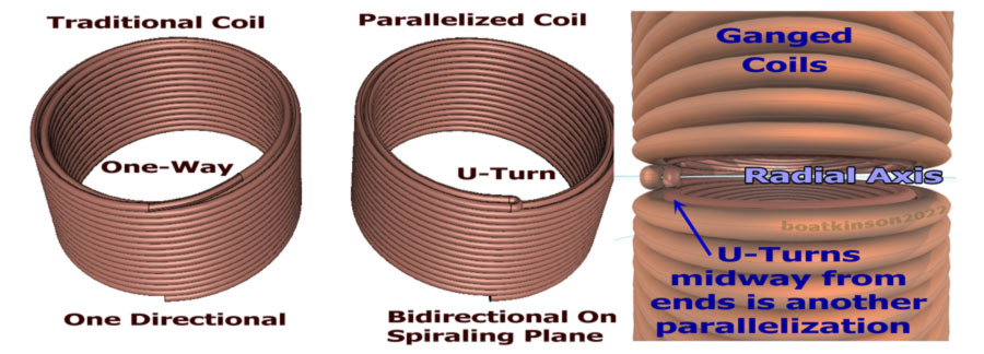
Later in 2016, a radial magnetic pole was found emanating almost 360º around it's "split-cylindrically-parallelized-windings". This was a very specifically wound electromagnet unlike common electromagnets. Paralleling multiple coil windings almost 360º around a circle, and there reversing electrical direction, (as if making a U-turn), back and forth around the same circular axis, to form a cylindrical shape overall. My quest for isotropic directionality of electromagnetic fields found new puzzles to sort out. This extraordinarily radial, magnetic-axis was captivating at first, (as originally posted in 2016), and then was later found more complicated, due to a critically adjusted relationship between two magnetic axes, (but it has not yet been finely determined).
Multiple variations of comparable coil forms were made and were observed to reveal the criticality, while not disqualifying it's variances due to wrong adjustments. Initially, the goal was to induce dominant, one-way, magnetic flows, for coil constructions. In some cases at specific voltages, (with sufficient physical isolation from other influences), the one-way dominant effect is clearly observed with a compass, even today. Setting up replications is tedious and this recommends a better apparatus to check all parameters continuously, instead of clipping and un-clipping wires, breaking fine wires, tangling up the work space with stray fields. Designing a lab-like framework should accommodate several versions of coils. Most important would be digitally logging all the parameters as experiments proceed. Otherwise it is useless to guess at properties like frequency, resonance, inductance, resistance, voltage and field strength, if there is no recorded log for future reference.
Above: Self opposing magnetic fields must have been one of the radial pole causes, (also observable with two opposing, permanent magnets), and this effect had "leaked" out my parallelized coil. As illustrated (too the right, below), an experimental coil can make two U-turns in one parallelized coil. The plane of parallelized wires can be orthogonal to the coil, (which was the primarily intended, dominant magnetic flow). The parallelized plane may actually form in at least two ways. Modifying an ordinary cylindrical coil pair, side by side, wires are simply reversed in direction, (below middle example which was the original attempt at one-way parallelized magnetic flow induction).
That most unexpected and perplexing, additional-flow-effect was originally posted here, which was somewhat misleading at first, (but it was soon afterwards realized and resolved). The surprisingly mistaken observation was simply due to specific tolerances of winding accuracy, and otherwise two distinct effects may become exploited, instead of just one, and the further realization was explained here. The two effects may be distinguishable as "a radial pole effect" versus "a dominant field-flow effect". These differing effects are distinguished by fine tuning of winding position of parallelism, the full explanation of which deserves more testing.
Before the parallelistic coil discoveries, a powerful helix tool in formZ software, (for 3D geometry modeling), had opened up an a very unusual avenue for coil explorations. The convergence of a trihedra and a helix was discovered, already preexistent in this same geometric tool, based on built in code, at a specific tool setting in the formZ app. The versatility of switching a three cycle helix from smooth line geometry to a 9 step faceted helix, coincidently produces a surface solid. When the resulting object is edited or exported to another 3D app, this object becomes a one degree curve, and looses it's convergence scaling, but nevertheless it can resembles both a helix and a trihedral surface solid.
This long pondered geometrical finding has finally found a physical application in the 2022 isotropic coil test. As a geometrical finding it may be both tetrahedral and trihedral because both word definitions do fit.
I will paste a link here for online discussion on these coils
at Field Structure Institute, if that can be set up.
Others are welcome to join in the a discussion and in experiments, on an open source basis. My reporting of effects is only at a preliminary stage due to ailing equipment, and therefore reporting is generalized on my webpages. The work continues.
This link goes to my long standing index page, (admittedly still needing better formatting).
Note: The content on this website, http://harmoniouspalette.com, is placed in the public domain as a free exchange of ideas and as a wish to serve life. The author assumes no responsibility for the improper use of the concepts in these web pages. All relevant laws of life and local codes should be verified and observed before any building or experimentation proceeds. Email discussion related to the content of these pages is welcome. Bo Atkinson
![]()