2016 Dipole VS Radial Coils
By Bo Atkinson ~ Also Edited in 2026
2026 Edits Continue while the experiments were never satisfactorily continued: Dipole, electromagnetic coils are expected to have one, central, magnetic axis. Here was a simple, experimental coil which seemed to offer a complimentary, orthogonally aligned axis.
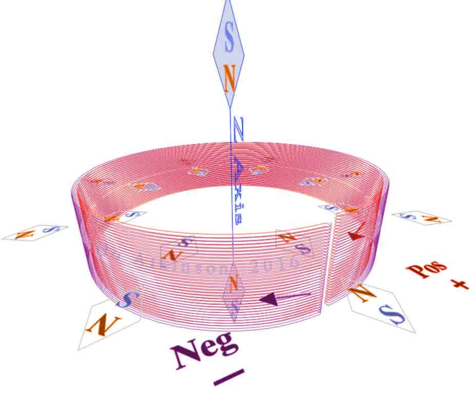
The schematic shows the folds where the inner and outer sets of parallel-wire-turns meet. Folded, speifically-paralleled, contiguous windings introduced different field observations than do one directional windings. An insulated, split-ring seam is indicated by the white space at bottom of this overhead view. We need to refocus here, on the fact that each-coil-turn folds back upon itself, in parallel, before beginning the return path, (and in this case no other windings are used). In the above 3D model, (drawing), the lowest two compass indicators have a question mark, to indicate my observation, that the seam alignment can vary, depending upon the tightness and positioning of this folded-end seam. As drawn, the open-spot reverses the “seam polarity”, because of the gap-space. Whereas very forceful tightening, of the insulted gap, showed that the magnetic field is somewhat adjustable.
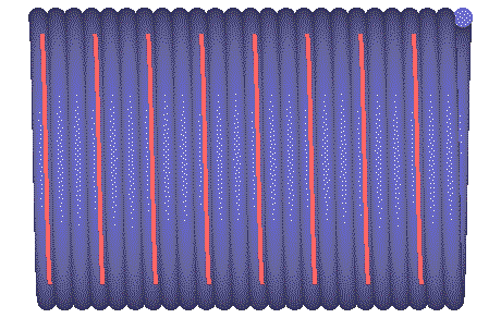
The inside coil-turns are colored red in this 3D-geometry model. The outer coil-turns are purple, (only to aid visualization). All these turns represent a contiguous, inversely-folded, wire coil. I have noted that these effects are dependent upon symmetrical turns... Hurried work resulted in some wrongly crossing turns which spoiled those results, while using (finer) #25AWG. I need to improve my tools. My first radiicoil (earlier photos above), easily folded-up symmetrically, with #20 AWG wire. (See tools further below). My mini-compasses were cheap and some of these failed to point precisely north and south. I chose a set of these mini compasses, which largely agreed in their needle direction.
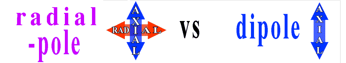
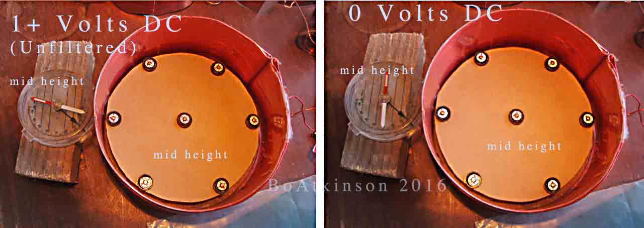
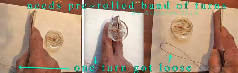
I chose the name “radiicoil”, because the radial vectors are a bold new characteristic. My expectation is that the radial field, may radiate spirally like the symbol from a book cover, pictured above. The spiral might oscillate directionally with alternating current. Next below are some photos of my sportsman’s compass, which show my unusual axial field alignments. (Same coil used as in the first photo, with #20 AWG wire.)

The photo sequence above shows the pass-through of a compass. (Or actually the girdling-past, by the moving coil, with the same effect.) Note how the field defies ordinary axial alignments. The white end of compass needle points to center, at both ends! (Needle reverses if Pos and Neg terminals are reversed). The brown tape holds the folded ends together. These two coil versions were energized with a wall type, un-filtered, DC transformer, (with open circuit at about five volts, closed circuit at about one volt). Next photo below shows the same sort of parallel folded coil, (but with #25 AWG wire), rolled up in snail like spiral fashion. The radial vector is lost in the rolled up versions.

I also tried rolling metal foil, in between… In these rolled up trials, the resulting, axial-only, field alignments were much the same as found with ordinary dipole coils. The radial field was lost. (Note that each end of these rolled up versions possess normal N-S poles, as expected with ordinary coils.) My preliminary conclusion here was that the “parallel radial effect” was cancelled by the continuous roll which laminates layers of doubly-opposing fields, close together. Thus, the “parallel radial effect” cancels itself. I have not tried AC with this rolled up version, instead devoting all my time to the fascinating radial field instead.

Photo above shows unusual, preliminary trials of one AC effect. The secondary or pick up coil was aligned at various points along the radial plane. (The same radiicoil is used here, as appears in first photo above). I am attracted to harmonic resonance effects, from simple coil geometry, (as contrasted with other sources of harmonics). Coils suggest more-direct interactions with most basic force. In a short time, some good harmonics were noted (in the photo above). Unfortunately, my latest acquisition, (a surplus HP 8116A pulse generator, as used above), came in the mail, partly dysfunctional. (Further explanation is at page bottom).
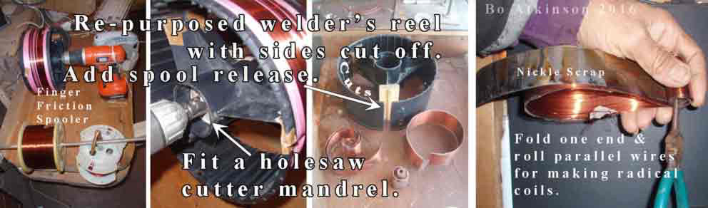
Above Left: Some of the quick methods used to wind the ordinary source coil, (before flattening this ordinary source coil into a flattening band of parallel turns). Needle nose pliers on right are beginning a tight roll, for the #25 AWG, into a snail like spiral, (as seen in photo before oscilloscope photos above). I made just a few tidy coils so far, before focussing on writing this complex webpage. An important technique is to crease and fold just one end at first. Hold the creased end, firmly-straighten and roll from that end only. This method allows the outer band of wires to develop the required, longer, close-fitting circumference wires, (or bands of wires). Once the flattened and folded band is formed into a radiicoil, with two creased ends, it becomes difficult to change the diameter due the creases. So crease with care. Transparent tape was used to hold all paralleled wires in place. Thus, parallel, folded bands fit tightly together without wrinkles. Wrinkles and misaligned bands of wire could otherwise diminish or ruin this effect. The next images suggest induced magnetic fields in the grey color. The brown color represents the radiicoil.
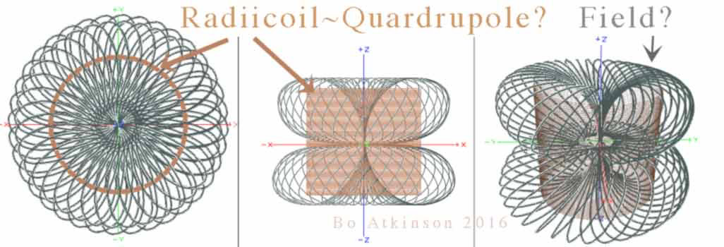
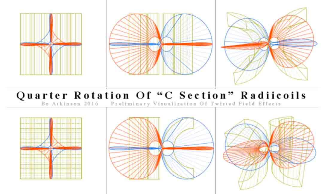
Images Above: Visualizing flows of forces suggest new coil shapes for me to work out physically….
Next image below: Without expecting anything like a quadrupole… I had initially expected that both inner and outer magnetic vectors might-possibly flow in the same direction, due to the left hand rule for electromagnets. Instead a surprising radial pole results, from self-opposing poles inside.

Perhaps the outer, longer circumference overpowers an immediate inner circumference which exerts a lesser field. But my last test at the bottom of this webpage actually challenges this reasoning. An additional assumption suggests a diamagnetic field effect upon the diamagnetic copper, according to battery polarity. Note on drawing above: The single, drawn "C sections" should actually represent multiple turns. My test on actual single turns was not so clear or not immediately so.

The individuated-parallel-radial-turns, if carefully arranged, do seem to magnify the radial field significantly, as compared with the multi-serial-turns, as illustrated just above. Forcing two regular, opposing permanent magnets together, also produces strong radial compass alignments, (but permanent magnets are not practical coils).
Previously known coils, wound as illustrated above, might suggest a radial pole. My very limited first physical trial, with 18 turns resulted with far weaker, almost unnoticeable, radial effects, (on the compass needle). This might indicate a much tighter and weaker swirl of the radial vector.
Back to testing the full circle radiicoil in the first photo farther above. One test was full wave AC resonating. With my broken HP 8116A pulse generator, i was able to “sweep” frequencies up through 10 MHz easily. Just pressing the “auto-vernier” buttons sweeps the frequencies consecutively. Resonant peaks come and go. However,further ranging up towards 50MHZ was much more difficult. This was possibly due to my antique 465 Tektronix oscilloscope, possibly due to some missing ranges. Or does my generator suffer upper range glitches as well? I want to be fair with these questions.

Photo above shows the same radiicoil, as first harmonic photo, except here we have an axially aligned setup. Is there a curious bounce going on where two opposing fields equalize or meet? It will be more interesting to use a function generator with precise pulse shaping functions. I have been slow to read all of Tesla’s available writings, but have begun to wonder if he had used some form of traveling pulse- rings, powered with his vacuum tubes and mercury-based oscillators, but this is going astray from my radiicoil work… In fact, my experiments posted here are all done with low voltages and with weak DC. My radiicoil exhibits little or no visible magnetic pull on crushed, unmagnetized iron, (also, at about 1 volt). Perhaps ordinary compasses are more sensitive than my crushed, iron slag particles. Or what? A diamagnetic electromagnetism? I wonder.
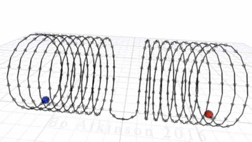
The animated visualization of “single turn pulses”, passing through an ordinary coil.
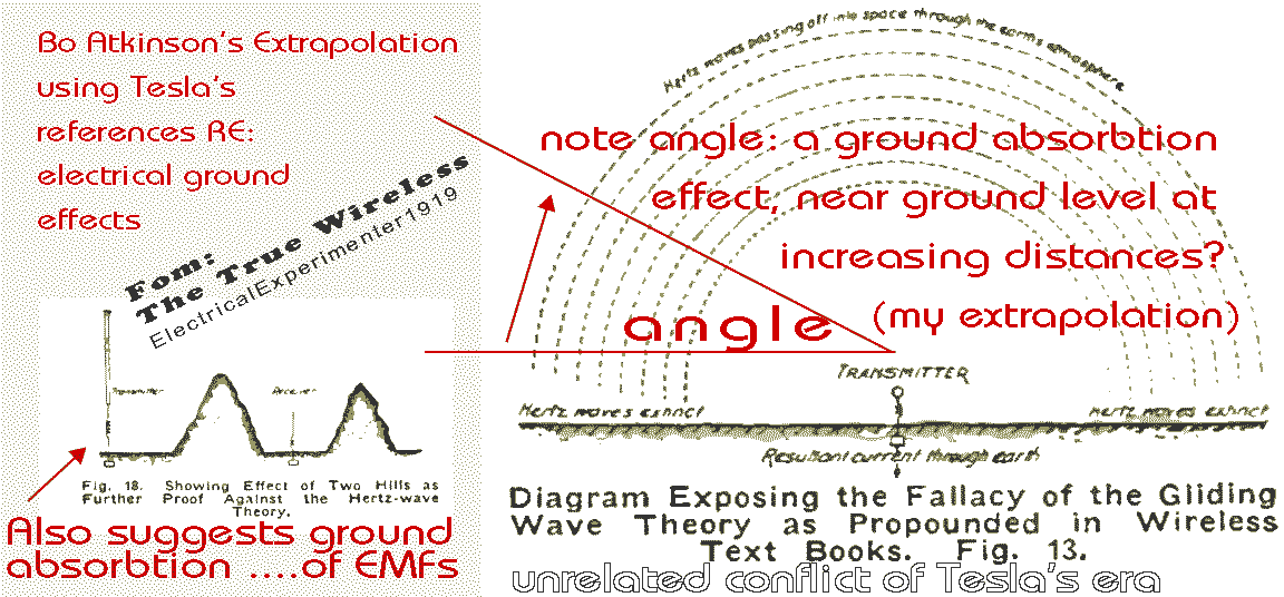
Next below is an additional graphic. It emphasizes individual turns, again, to fit symmetrical, individual pulse segments.
I readabout Tesla’s saga with his ground waves. I was moved to imagine ground waves and air waves interfacing inside one radiicoil. I wondered if he had used opposing field vectors in a coil. His 1894 coil easily self-opposes the pole vectors, while still increasing self capacitance, due to closely positioned negative and positive peaks. Check out the wording in his patent. Has anyone tested this “S version”? (Depicted bellow to the right.)
My lesser coils need much more work. Higher voltage levels, longer windings and magnetic core options all deserve experiments. I tried connecting an 18V LI, (DC) battery to my #20 AWG radiicoil. The coil heated up too quickly, as it dumps too much DC current into 20 AWG copper coils, without the useful reactance of AC power. Still to map out more carefully, is the variable radii effect, obtained by splitting open the seam. Variable radii deserves much closer attention.
This turns us towards practical testing of segmented radiicoil sections. Next action photos below demonstrate the peculiar field of a “flattened but previously rounded coil”. (I have been hurrying to publish this webpage, while additional ideas continue brain storming.) With initial, expedited testing, generally flattened ordinary coils also challenged the left hand rule! I observe that this level of disarray still provides curious results. I wanted to quickly observe the compass reaction with a flat band of parallel folded wires. I have had enough of hurriedly cobbled together winding setups. So i just re-flattened my #25 AWG coil instead. We need further verifications. Patience. Due to previous rolling up, with tape, the result was a rumpled. Despite the crude un- rolling, (of previously rolled up band), these were the observations, displayed in photos below:
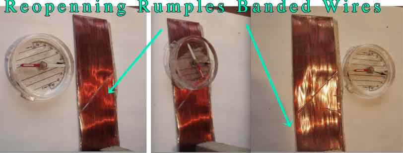
Hand held camera left me just one hand available to steady the band of parallel wires. The compass reading on top of the band (not edge), seemed a little sticky, for the compass needle, (undecided?)… Yet if the needle could align with the rumpled wires, at all, this spurs my curiosity. Otherwise, could it be due to the relative position of the reading taken near to the far end of the band? (December 29 Note: On further testing the compass reading at top of center photo does align with wires again, but just beyond the end point. I believe that force fields are curved and are not linear like compass needles. Also these particular forces exert very small physical effects.) Flattened wire bands (similar to these photos), seem to suggest extreme coil radii.
{December 31, 2016 Addendum} Tesla researchers somewhat might say that so called "air waves" utilized in radio transmission, were and still are a greatly wasted energy resource, when much more benefit could be had with more benign and globally localizing ground wave modulation and demodulation, of energetic waves. Would these have been associated with figurative “free energy”?
Did Tesla utilize ground waves, to trigger modulation and demodulation, of forms of energy, into currently servicable, electrical energy. For an infinitely superior "prime mover" to first be recognized and tapped, for electrical energy as a received service. To inaugurate the use of wiser energy sources, loosely referred to as 'ether', (as inferred by Tesla and earlier scientists). To accomplish this phenomena locally, (everywhere locally) and not to remain reliant upon direct, resistive, line of sight transmission-reception schemes. This argues against a need to reflect radio waves off the ionosphere, or to confine signals or currents inside of closed networks, or to render the atmosphere electrically-conductive, with geoengineering, aerosol spraying, pollution, etc (the action of militant investors who attempt totalitarianism through mind interfacing and soul hijacking, in programs with names like TAM I, SATAN, etc)...All of which additionally poisons life and causes ecocide of an otherwise wonderful planet.
This webpage was first posted on the internet on December 28, 2016.
Note on my partly broken function generator: It’s shipping box had been torn open (and it's packaging filler had been partly removed, see next photo below). Was it broken) during shipping? This particular model was designed with special protection circuitry, but not enough to withstand direct connection of the front panel terminals to full AC line current. This function generator was offered as a low cost bargain, from an ebay approved, US source, which alternatively could imply the risk factor with surplus items in general. However, why was the end of the carton and also some internal packing material permanently removed? The delicate instrument was loose to slide around inside. Also, why had it been delayed a long time in the US postal system? Here is a photo of it’s wide open condition, directly after it’s long delayed arrival:
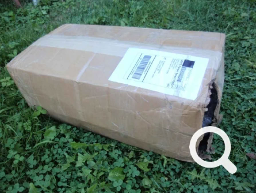
I did not trouble my local post office with complaints. I believe these are good people just doing their job. I accept risks. The surplus vendor and i had opted to save money by avoiding extra insurance. Graciously, the vendor offered a partial refund. (We shared the risk and loss). Unfortunately, my good function generator has lost critical pulse timing, (according to the manual instruction procedures). I wanted to shape the pulses precisely and symmetrically, to advance these experiments much further. I felt this is just one small sign of our failing world condition May we heal society? I try to work towards that end.