A guy from a disadvantaged country asked for thin shell dome plans which he could built at low cost. He emailed me because he recognized the probability of low cost materials in wire ring reinforcement (ringforcement). (Or, at least he complimented my structural concepts with the term "autonomous" ;) He wanted to build an "ostava" (translated: storage shed). We traded a few emails and he sent me 2D dome specs which I developed in 3D as follows. (Later he offered some mathematical solutions for pentagonal tessellations, as he is a professional mathematician. This page should be rewritten for pentagonal panels but no time is available here, to do so). More details will be added eventually, visit again. This is an unfinished building concept under construction.
Following is a building system for small ferrocement domes, in which ring like, flattened, continuous wire reinforcement is used. This is an experimental system striving to use a minimum of material for maximum benefit. Wire is well suited for thin cement because multiple, overlapping strands can be embedded in thin cement panel sections, (without interposing shear planes). Structural stresses are gently distributed through multiple wire curves. Structural settling and cement shrinkage are both eased. By comparison, continuous reinforcement bars do not adjust as well to shrinkage or settling of thin shell structure. An equivalent mass of closed looped reinforcement rings can be determined to match any ratio of steel to stone.
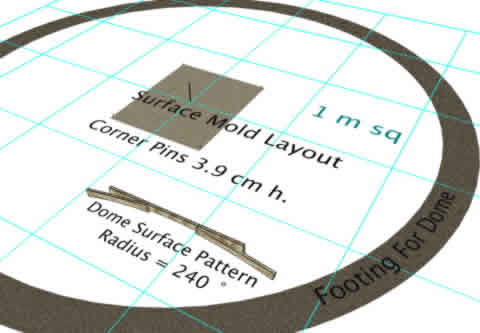
In this building system, one panel section is added at a time. First, one or more mold sections are made on the ground. A simple wooden arc pattern is pivoted around a center pin. A constant radius will ease the following steps, at least for explanation purposes. (Although a perfectly smooth structure is not necessarily a rule. Seam bumps on surface should be forgiven for the difficulties of developing new methods. Besides, crude surfaces actually can lend appealing characterization. If building kits or better tools were available, perfectly smooth surfaces could be made competitively with other smooth building systems.)
The dirt is packed and mounded. The wooden arced screed is used to establish curvature of dome surface by spreading the dirt while pivoting around center stake. Four pins are driven into ground and leveled. Pin placement is set for each of the 4 corners. (Door will subtract from this. For the successive tiers of panels, this mold should be trimmed to allow fitting close to previous tier. Trim according to dimensions in the unfolded pattern below). A simple compass can locate the points, but accuracy is not so critical with this method. The shingle effect overlaps panels to provide a weather tight seal. Getting the work done somewhat crudely is recommended over obsessive accuracy. Using a cloth tape measure will work adequately. Under-sizing will allow tilting together of panels). The shingle effect will fill gaps.
.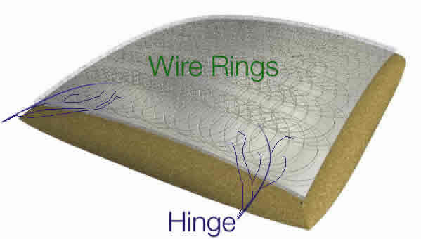
Rings are embedded in wet cement placed on dirt mold. Mold hinges are stranded cable. Embedded end is unraveled to distribute stresses within the thin cement mold. Other end of "cable hinges" can be anchored to floor or to staging. (For floor: drill tight hole and insert cable therein. For staging the cable can be clamped or bound to staging legs.)
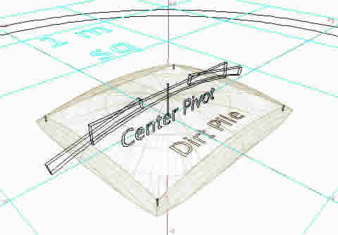
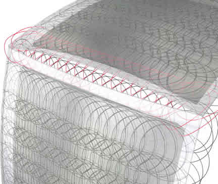
Geometry for manageable, easily lifted panels follows. The same mold above can be used throughout dome. Two of the top triangles can be molded at one time.
The point of this geometry is to find corners on the mold surface made in pictures above. Short nails or other objects can be used to permanently mark these corners. Place them when the mold still has wet cement. Edge lines might also be drawn or lightly inscribed. Next below is the "unfolded geometry" to give dimensions assuming a 5 m dome.
Picture below shows stones used to hold wire. Welding wire has been selected for high strength and bulk availability. It is stiff, but with practice and care, it can be embedded in wet cement which will hold the springy wire securely. Stones can be used but with practice wet cement anchors wires while they are arranged. I've been arranging wires a little crudely and am satisfied for the present since I want to finish the work without too many delays for better tool construction.
After curing the mold(s): A tilt up method is used to patch together the dome surface. The mold is hinged in place. The wet tilt up is suggested in this system because the number of "cold joints" is reduced to half. Also a smoother seam is possible between panels. Tilt up method uses gravity to assist in compacting low water cement in place with less losses. A shingle style of overlap is recommended to increase bonding surface at panel seams. Also the desired overlap of rings between neighboring panels is achieved. The first row of panels will need added mold support to stand upright. A foam rubber pad, such as a recycled bed mattress is recommended. It may be braced or tied in place. Bo has used specially made clamps to hold steep, wet panels and keep them from slipping off nearly vertical form work.
The mold is left in place until the initial cure is complete. After curing the mold is then moved into the next position. Sticky sand, dirt, fabric or other mold releases aid removal from ready dome panels. Plain cement mixtures without additives are possible if curing is well controlled. Especially with thin cement structure, the aggregate size should not exceed 1/3 the finished thickness.
2007 focus on fast-&-easy ringforcement flat work.
2005 experiments with hand made mesh may be seen here. (Click).
Pre 2004 mesh forming methods are linked here.
I prefer cork screw and hollow screw mixers. For thin ferrocement work, screened sand used with brick masonry is often best. The main rule of curing is to hold moisture in. This system allows gap- free covering with plastic sheet because there are no continuing rebars or meshes to interfere. For dry climates, a dampened, wet cloth underneath the plastic sheet will better ensure damp curing.
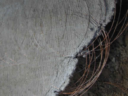
In picture of real cement panel above, it can be seen that rings have been spread unevenly. For lack of better tools and jigs, or the time to develop them, this author has been content to try building a 10m ,(30ft) dome, with unevenly spaced wires. Before tilting up the wet panel, the cement is spread on, along with installing the wire reinforcement. Several overlapping layers of wire ring-loops can provide good 3D distribution of reinforcement throughout the thickness. Exposed wires can extend beyond the mold to overlap adjoining panels. Next the wet, reinforced cement is tilted up into place. When the wet panel is in the proper place, more cement can be applied to the overlapping seams). A small amount of rust may form on exposed wires, if time passes between lapping adjacent panels, but this is not a problem. Surface rust on the wires or copper or galvanized coatings are all equally acceptable in authors mind.
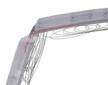
The over lapping rings of the fresh, wet panel can be bent together with exposed rings from existing panel below. Picture above attempts to illustrate the bent rings simply tucked behind rings below before or during fresh cement placement. The bent rings are colored red to better identify them. As the panel tilts into final position, the wet cement allows rings to finally relax. Then the cement can be smoothed. (See recommended smoothing technique, (click here),for ferrocement uses).
High strength steel like welding wire offers ultimate efficiency except that
it is very difficult to handle. FIne wire distributes stress but fine wires
being more numerous adds difficulty in ordinary hand labor. Manufactured
meshes are popular and offer some convenience. Welded mesh is generally
thicker than ideal and not ideal for shrinkage or settling. Chicken wire
fencing
also looses
some "ultimate
strength" due to wire
consumed in the tying together of mesh segments.
Notwithstanding market forces and subsidies which artificially distort actual material costs, it is here suggested that plain wires or continuous filaments are the most efficient materials. Manufacturing efficiency is better, but commercial distribution of wires generally lags behind, due to traditionally low demands for light gauge, high tensile wire. Such wire is available from welding suppliers, (but unfortunately is difficult to hand- coil). . For larger projects, it is well worth bypassing retailers and seeking distributors willing to sell large spools or pallet loads. In America a very competitive dealer was found who sold .035" diameter (.889 mm or .9mm ?) welding wire near 50 US cents per pound, (in pallet lots of 108 plastic sealed spools, each 33 lbs or 15kg). More details on wire handling tools and jigs for this system will eventually be linked here. A page detailing some conceptual wire handling tools has been started.
Presently a few things are lacking to fully prove this system. Tools for
wire handling and better market distribution of wire present one obstacle.
Continuous
filament such as PVA could simplify construction but is not immediately available.
A PVA or equivalent filament might be easier to embed than is steel wire. Ultimately,
mass produced closed "O" rings, manufactured in one step without
post processing, would improve thin shell production efficiency. Cheap "O" rings
used as aggregate are a special conceptual goal of this system. In the meantime,
wire is used as the best available alternative. Jury-rigged procedures are
used because this is still a prototype system.
Slow, short cycle work sessions are adaptable, so that one person could do this alone (or with some helpers). The system could also adapt to massive form work structures and quickly cast whole buildings.The work could progress in small sections with less losses due to "cold joints". By contrast, continuous reinforcements like bars, and meshes further constrain builder flexibility. This is only a free exchange of building concepts, no guarantees are made whatsoever.
Too little is known about actual test comparisons between traditional reinforcement, flat spiral loops and individual "O" rings. Rings appear to have interesting test possibilities. As a low budget single handed developer, I have very little opportunity to test the many ideas presented in these www pages. The testing cannot keep up with my my conceptual exploration.
The content on this website, http://harmoniouspalette.com, is placed in the public domain only as a free exchange of ideas and as a "hard studied wish to serve life". The author assumes no responsibility for the improper use of the concepts in these web pages, as all relevant laws of life and local codes should be verified and observed before any building or experimentation proceeds. discussion is welcome, please write. Bo Atkinson