Here are some ideas for building cementitious vaults. This page features CAD models of vaults using strong, lightweight, ferrocement. First a height saving vault is shown which can be scaled taller. Further below, subdivision framing is presented of this flattened vault style. The first picture scales the same CAD model. First some height is scaled. Next the high vault is scaled narrow. Improved span capabilities and larger thermal exchange surfaces are considered here. While the vault surface can be thin ferrocement, the mass between vaults can be compacted soil materials.
Next below are shaded renderings of subdivided vaults which incorporate frameworks. The first computer rendering shows that the low height vault can be subdivided while using organic patterns.
. Next below, the patterned form work is visualized from above.
The molds visualized above would be filled with cement, concrete and reinforcement , (according to proportioned, engineered specs). Below, the cement is visualized, covering the molds. Dense infilling with concrete and steel reinforcement could comprise vault surfaces shown below.
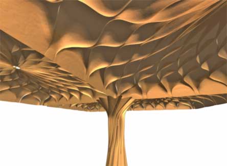
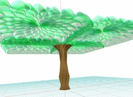
After filling with cement above, the voids could optionally be filled with lower strength- lower cost concrete, in order to level as for a floor surface. Next below the computer model is rendered in green to suggest a leafy tree-like to a vault ceiling. Coloring and texturing of cement could suggest a variety of appearances.
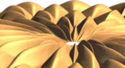
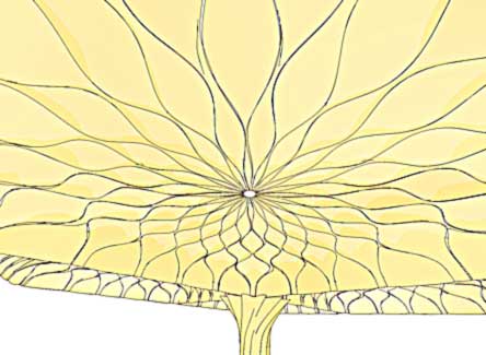
Next, a computer sketch of the outlines also can look like a sun flower seed pattern.
Next below, methods to support the work is shown. Poles are used to tilt up and hold sections, in place. After cement is cured sufficiently, the poles and molds are removed. Gel coat application can color and texture the exposed surface in "fewer steps", reducing the application of finish work from below. Alternatively, the"molds" could instead be finished tiles which stay in place.
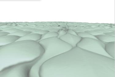
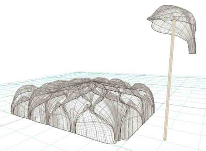
Below, sub-division sections are portrayed on ground, as if clustered on a sand mold. (Wire frame display again). A single section is shown atop a pole as it would be placed overhead in final vault assembly. This particular section was measured by CAD and weight for a finger thick version might weigh between 60 lbs and 30 kilos, not bad for vaulting into place!
Computer models like this can otherwise be sent to fabricators to produce accurate molds, directly from computer files. New fabricating technology can reduce human error and hundreds of man hours.
Too little is known about actual test comparisons between traditional reinforcement, flat spiral loops and individual "O" rings. Rings appear to have interesting test possibilities. As a low budget single handed developer, I have very little opportunity to test the many ideas presented in these www pages. The testing cannot keep up with my my conceptual exploration.
Note: These pages are placed in the public domain and are furnished "as is". The author assumes no responsibility for the use or misuse of the concepts in this series. All authorities should be satisfied first, as might be required, by relevant laws, before any building proceeds.
Searching Synergy .... .... Free Exchange of Ideas
Email comments welcome ~~~~~~~ boa1@pivot.net
Tel : 207 342 5796 . . . (Maine)